Testbench architecture – Layered view
Layered view of test bench is grouping of the related functionality components into five layers. In the following article let’s look at what these…
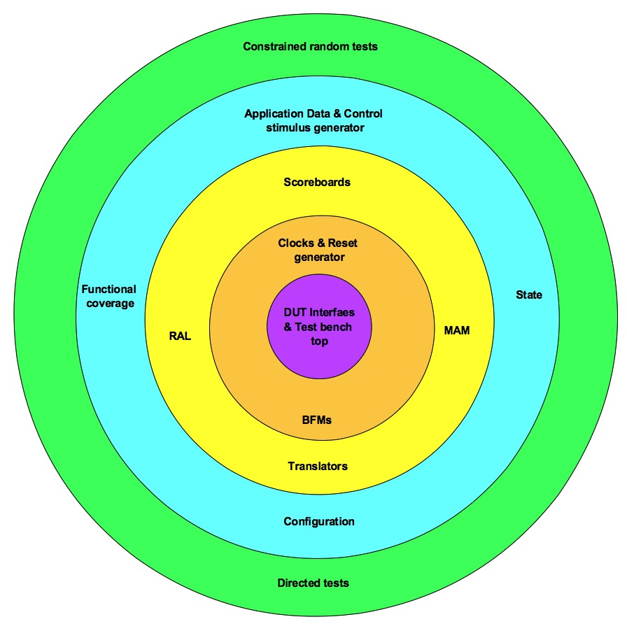
Layered view of test bench is grouping of the related functionality components into five layers. In the following article let’s look at what these layers are and what are the group of components in each of them.
Layer#1: Test bench top – Connecting DUT to Test bench
Test bench top is container for connecting the design under test (DUT) to the test bench. Typically the HVLs provide way to encapsulate the related set of signals as interfaces. This allows passing related set of signals as single unit. Encapsulate related set of signals in to different interfaces of the design. Parameterize the interface to suit to various interface reuse needs.
In the test bench top module connect interfaces to various design’s ports. These ports are passed to the test bench. Test bench interacts with the design through these ports.
Any other small glue logic required for connection of the design and test bench can be included in the test bench top.
Generally test bench top ends up getting touched by multiple participants. Care should be taken to maintain the cleanliness of it.
Layer#2: Bus functional models – Signal interface handling
BFM is an engine that powers the test bench. Bus functional model (BFM) converts the signal level information to the transaction. Transaction is further processed or issued by the next layer test bench components. BFM architecture itself is area by itself. General expectations from BFMs are listed here.
Test benches especially the object oriented programming based languages are driven by concept of “transaction and transactor”. A transaction is encapsulation of the information. Transactor executes the transaction. A transaction is like an instruction. Transactor is a like processor that processes the instruction.
This concept is repeatedly applied in all the test bench components. Even within the BFM. BFM acts as a transactor by processing transaction issued by the test bench.
Layer#3: Translators – Application level to BFM Transaction
Translators translate the application level stimulus to transaction level stimulus. Transaction level responses are converted to the application level response. The question that comes up is, what is application?
Applications make use of designs. Real value of design is realized in application. For example a USB device design used by flash storage will utilize USB serial physical transport for transporting data based on SCSI protocol. Application level SCSI protocol runs on the USB protocol. This is made use by the operating systems to provide the file read and write services.
End application on operating system, can generate file read and write type of requests. Drivers generate the SCSI commands corresponding for the same. The SCSI commands are translated to the USBx transaction stimulus. Here the application level stimulus of file read or write is broken down to the set of the USBx transactions. This high level stimulus to transaction level translation is grouped in as functionality of translators.
There can be complex or even simpler translations required to convert the application level stimulus to transaction stimulus. USBx and SCSI example can be debated that SCSI to transaction translator can become part of BFM itself. BFMs themselves can raise their abstraction up to application level. When that is not the case the translators in the test bench will have to handle the conversion. A high level stimulus is generated which is more in-line with the application world. This stimulus has to be converted to the transaction interface required by the BFM using the translators.
There can also be additional controllability added in the high level stimulus to make the process of verification easier. This controllability handling is also implemented in the translators.
RAL and MAM aid the translators. Translators use the services of the RAL, MAM and BFM in implementing their functionality.
Register abstraction layer (RAL) abstracts the DUT’s registers. It converts the access to RAL model by test bench to the actual read & writes transactions to DUT registers. This abstraction also helps in making the address space change and physical bus change agnostic to test bench.
Memory allocation manager (MAM) translates the memory allocation and deallocation requests to real address region allocation and deallocation. Combined with MAM is system memory model. This is required for the design’s requiring the system memory model.
Scoreboard is another translator that implements the translation of the data done by DUT. The input of the DUT is captured as reference data and output of the DUT is after translation compared to the actual data.
Layer#4: Generators – Stimulus and Coverage
Generators are top-level verification components that generate both the data and control command stimulus generation. Both the data and control commands are modeled using the transactions. Transactions have constraints to constrain the variables of the transactions. These are randomized on every stimulus transaction generation.
There are some of the parameters that get randomized only once during the initial start of the system and remains same thereafter. These are captured in structural and functional configurations. Some of the examples of the configuration parameters are minimum and maximum size of the data traffic, highest number of the ports allowed, various timeout values. These configurations are used in the constraints of the stimulus transaction generation. For example the random size of the data traffic generated is constrained between the minimum and maximum data traffic size specified in the configuration.
Some of the stimulus generation may not only be configuration dependent but also system state dependent. For example USB host data traffic cannot start unless the device is connected and initialized. So the data traffic generator has to wait till the device is connected and initialized. Such synchronizations are achieved by maintaining the system state. State is typically maintained as shared object protected with semaphores. Its updated and used by different components of the test bench for synchronization. The information in the state object also used in the constraints of the stimulus transaction generation.
Any constrained random testbench should also be supported with the functional coverage. Constrained random by default has the uncertainty. An intended scenario may or may not happen. So ones, which are critical or important, should be confirmed by coding the functional coverage. Functional coverage should be cleanly abstracted off separately from the test bench. This also allows easy porting of the functional coverage to other test bench environments when the need arises.
Layer#5: Tests – Controlling stimulus and configurations
The stimulus generators and configurations are the knobs provided by the test bench. These knobs are to be controlled by the tests to achieve the verification objective. Tests will control the test bench with the various knobs provided by the test bench. Tests will override the constraints of the stimulus transactions and configurations to create the scenario of interest. Test will utilize the state and events provided by the test bench to achieve the synchronization with the test bench to control and synchronize the stimulus generation.
Tests can be either constrained random or directed in nature. Both of these forms of tests will utilize the infrastructure provided by the test bench to achieve the verification objective. Tests should be as light in terms of their code content as possible. Whenever there are additional test requirements coming in which are not satisfied by the test bench infrastructure, test bench architecture should be relooked. It indicates holes in the features provided by the test bench. Except few tests, which are testing a very corner cases, all test requirements should be met by infrastructure of test bench. This is important because it prevents bloating of tests and promotes the reuse.
Ideally tests should contain code to control test bench by APIs it provides. Test specific APIs implementation within the test should be minimized.
Even for the checks, test should rely on the self-checks implemented in the test bench. Tests can downgrade the checks wherever they are not relevant. Only corner case scenarios where the generic self-check inside test bench is not of sufficient ROI, it should be placed in the test itself.