Design under test (DUT) for Verification Engineer
Understanding design under test (DUT) is very important for verification engineers. Remember RTL design gets taped out as final ASIC product. Sales of this product brings…
Understanding design under test (DUT) is very important for verification engineers. Remember RTL design gets taped out as final ASIC product. Sales of this product brings in the cash that pays for our salaries.
Verification is activity that trains DUT to make it fit for use.
Now key question from verification engineer’s point of view is, what aspects of DUT should be understood for purpose of verification?
Verification requires understanding of the following aspects of the design:
- Micro-architecture – Data and Control
- Interface to external world – signals and buses
- Programmability and Status
- Major data flow for key operations
- Implementation specific logic
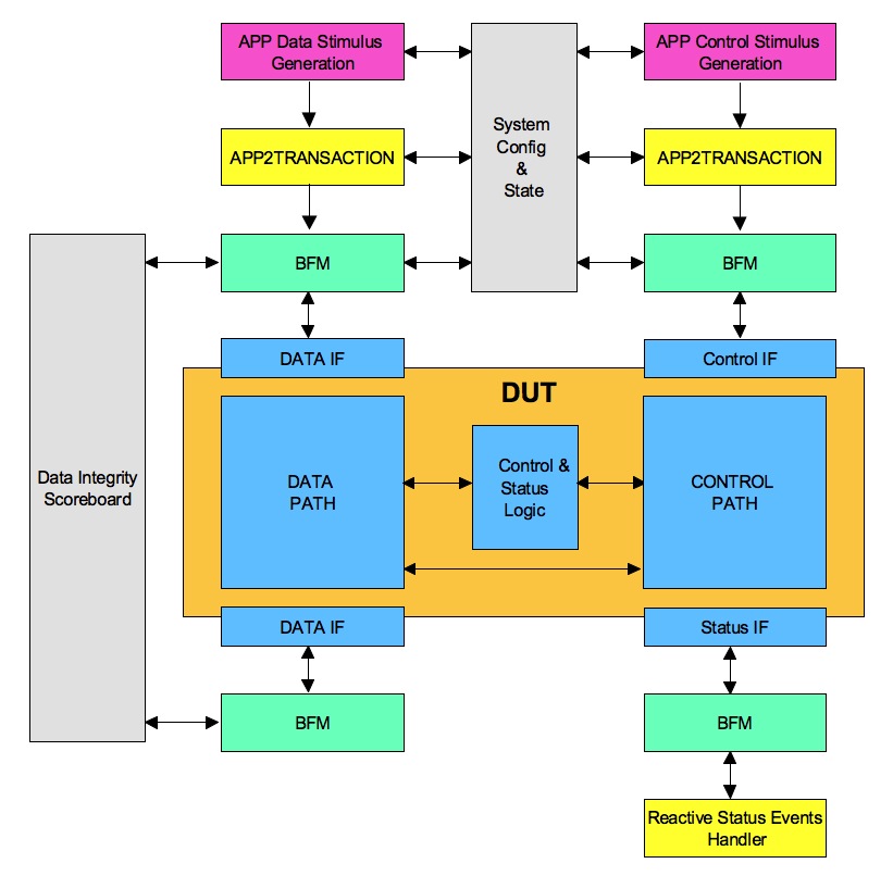
Micro-architecture – Data and Control
DUT micro-architecture is division of the functionality for implementation. One of the key component of micro-architecture is to divide it into data and control functionalities. A very simple view of design is to look at it as transfer function. Data path implements the data transformation functions. Control path controls the data path for achieving the configured data transformations.
Data transformation is primary functionality of the design. Control is an overhead to accomplish the data transformation in efficient and optimal way.
How is this useful for verification?
Verification of data transformations requires stimulus with various input data parameters variations. Input parameters such as various input data sizes, sequences, and delays between the data should be modeled. Data stimulus generator and sequences should be designed to meet these requirements.
Checking the correctness of data transformation is accomplished by checking for the data integrity. Design should be modifying the input data as per the transfer function defined. It should not deviate by modifying in different way, adding additional data or removing required data. Typically this is handled with the help of the verification component called as scoreboard. A scoreboard will keep track of the reference input data and compare it with the output data after transformation.
Verification of control path requires stimulus with ability to generate various input control trigger variations. Typical input control triggers could be low power request events, hot plug events, reset events etc.
Input control trigger stimulus generation is more complicated compared to data stimulus generation. Complexity in control trigger stimulus generation is due to their close dependency on state of design and system. Apart from state dependency, synchronization needs to be established with the active background data stimulus generation.
Interface to external world – signals and buses
DUT interacts with external world through its interfaces. Interfaces of the DUT can be in the form of individual signals or buses. Buses are group of signals governed by protocol for communication with the design at higher level of abstractions.
Application uses the design. Both the data path and control path have external interfaces for interaction with the higher layer application. Data interface is used for either pumping the data in or sinking the processed data out of design. Control interface is used for programming design and finding out the status of the design.
Data and control interface can be shared on the single bus in some cases or both the data and control path can have multiple independent interfaces. When there are multiple independent interfaces the concurrency and any relations among them should be taken into consideration.
How is this useful for verification?
A bus functional model (bfm) is attached to each of the interfaces. Bus functional model handles the interfaces and also does the checks to ensure the compliance to the protocols of operation defined for the interface.
Typically bus functional models (BFM) provide the transaction interface. Both the data and control stimulus generators provide the transactions to BFM and BFM drives them out to the interface. Also response from the interface is converted to the transaction by the bfm.
Any synchronization across interface or checks spanning across multiple interfaces will have to be handled by the additional verification components in the test bench.
Programmability and status
Programmability and status of the design is typically implemented with the set of registers and set of status events. Registers are accessed like memory. Read and write of the control and status registers provides the required programmability and insights into status.
Control registers allow configurability for the programmable features and parameters of the design. Status registers are used for checking the status of the various key blocks and health of the design. Status events provide interface to notify about the status updates to application.
Control register interface may also be used for issuing commands to optimizing the operations and recovering from the error scenarios.
How is this useful for verification?
Register structure implementation used for control and status has its own verification requirements independent of design specific functionality. Ability to access all the registers, correctness of read, write (RW) access types for different bits and special access types such as read or write to clear needs to verified. Also the initial values post reset matching the expectation needs to be verified.
Typically programmable parameters of DUT are captured as part of configuration. The variables of configuration are constrained to the legal range allowed. Randomized configuration is then programmed to corresponding control registers in the design.
Status register verification is typically tricky. Set of directed tests, reactive components of the test bench and end of test check are used for verifying the status registers. Self-checking mechanism for all the status registers can be very complicated.
Typical output status events could be interrupt events, faults indication events and status updates etc. These are handled with reactive verification component.
Reactive verification component waits for the status events and processes them.
This reactive verification components will implement the abstracted application behavior for handling these events relevant for verification.
The check requirements on output status events can also be handled through the scoreboard concept. But these can become very complicated. This is because of complex dependency on implementation specific details. Successful completion of various application scenarios created requires the correct generation and handling of output control events. This can also be a good enough proof for the correctness of the functionality.
Major data flow for key operations
DUT’s usage by its application can have various frequently used key data flows.
These data flow paths should be identified and understood.
Data flow path understanding is about following the data flow from activation of external interface to flow through various internal blocks, transformations on the way and all the way back to its completion based on various responses.
How is this useful for verification?
Application level scenarios may require additional directed tests. This understanding can also help identify standard initialization sequence or any other operations that can be bypassed to achieve simulation time reduction for tests that do not focus on verifying these features. This enables running selected tests matching the simulation to real life application usage as closely as possible and rest can run faster with various bypass.
Understanding data flow details will also help enumerate the white box scenarios. Such as, what if the credits are all blocked? How to create scenarios such that prioritized arbiter has multiple requests active? How to create that FIFO overflow or underflow conditions? Etc.
Implementation specific logic
So far we focused on part of design that helps in achieving the functionality. But the silicon based design implementation itself requires some additional structures beyond functional RTL design.
Clocks and resets is one such item. There can be multiple clocks and multiple reset domains. Clocks have several attributes such as jitter, ppm and spread spectrum requirements. Resets will have synchronous, asynchronous and reset sequencing requirements.
Most of the designs now utilize low power techniques to reduce power consumption. Clock gating and multiple power domains are commonly used techniques.
IO pads and their verification is yet another area.
How is this useful for verification?
These additional structures do not directly contribute to functional verification but do affect the correctness of the functionality. These do give rise to additional verification cases, which must be verified to ensure these additional structures are functioning correctly and not breaking any other intended functionality.
Design for Testability (DFT) is another big area but this covered separately and does not fall in the bucket of functional verification.
DUT understandings will help greatly with capturing coverage requirements for micro-architecture which can help prevent famous bugs like pentium FDIV.
We offer test suite stimulus audit services through our analytic APPs that can help you quickly figure out if your stimulus is doing what matters your DUT.