PIPE 5.0: 34% signal count reduction for PCI Express 5.0
PIPE specification version 5.0 has been released on September 2017. Number “5.0” has special significance this time. From PIPE 5.0 onwards, supports or protocols is…
PIPE specification version 5.0 has been released on September 2017. Number “5.0” has special significance this time. From PIPE 5.0 onwards, supports or protocols is extended to 5 different interface protocols and it’s gearing up for PCIe 5.0.
Top 3 highlights of changes in PIPE spec version 5.0 are:
- 34% signal count reduction on PIPE interface
- SerDes support. PIPE width increasing up to 64-bits for PCie SerDes only
- Support for two new protocols: ConvergedIO and DisplayPort along with PCIe, USB and SATA
In the following blog, we would like to discuss more about the point#1, which is the significant benefit. Layout engineers will surely celebrate this change with many fat signals being moved to message registers.
There is 34 % reduction in PIPE signal count. In PIPE 5.0, all legacy PIPE signals without critical timing requirements are mapped to message bus registers.
Breakup of reduction across various signal categories is as following:
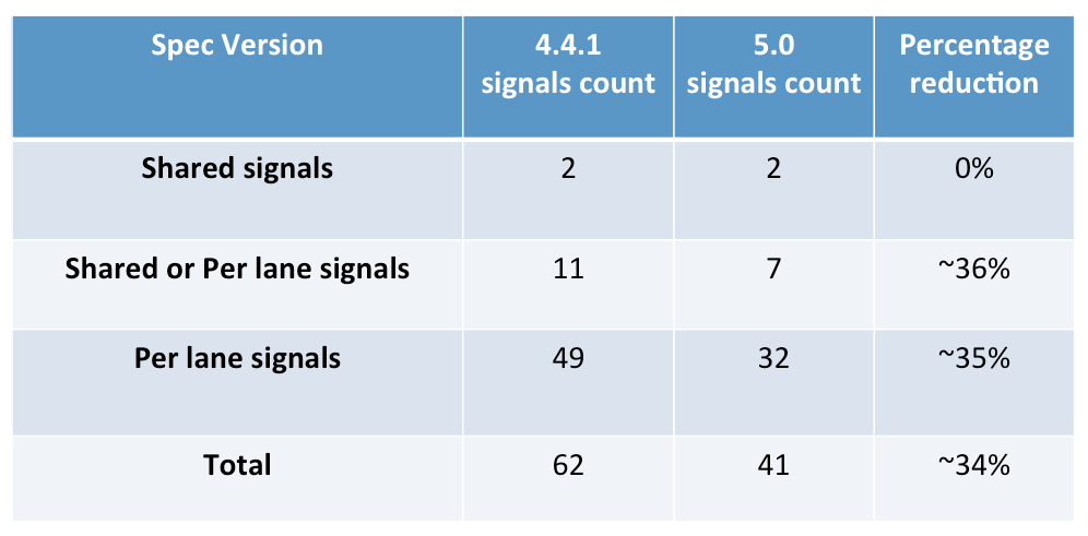
Signal count is number of logical signals defined in PIPE specifications.
Ex: Group of wires such as PowerDown[1:0] is considered a single signal in above counts.
From PIPE specification 4.4.1 onwards a new message interface was introduced. Any new features added from version 4.4.1 onwards will be made available only via message bus accesses unless they have critical timing requirements that need dedicated signals.
This pin count reduction implementation will be mandatory for PCIe 5.0 implementations. PCIe 4.0 can continue to use legacy pin interface. USB 3.2 and SATA can optionally utilize it.
Magic that makes this signal count reduction possible is message bus. So, let’s briefly look at message bus.
What is message bus?
The message bus interface provides a way to initiate and participate in non-latency sensitive PIPE operations using small number of wires and it enables future PIPE operations to be added without adding additional wires. The use of this interface requires the device to be in a power state with PCLK running.
Control and status bits used for PIPE operations are mapped into 8-bit registers that are hosted in 12-bit address spaces in the PHY and MAC.
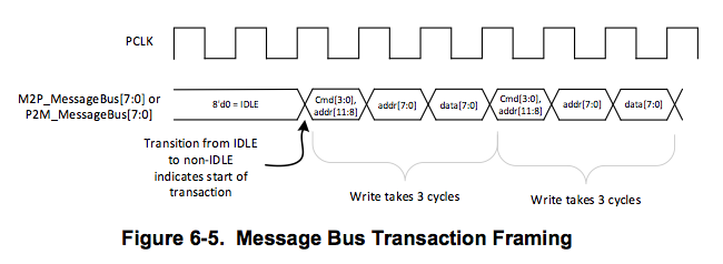
The registers are accessed via read and write commands driven over two 8-bit signals M2P_MessageBus[7:0] and P2M_MessageBus[7:0]. Both of these signals are synchronous to PCLK and are reset with Reset#.
All the following are time multiplexed over the bus from MAC and PHY:
- Commands (write_uncommitted, write_committed, read, read_completion, write_ack)
- 12-bit address used for all types and read and writes
- 8-bit data either read or written
A simple timing demonstrates its usage:
PIPE 4.4.1 utilized the message bus for the Rx margining sequence. This helped standardize the process to measure performance of link in live system. Performance of link varies due to crosstalk, jitter and reflections all which are time varying as they are subjected to PVT (Process/Voltage/Temperature) variations.
More information about message bus can be looked up in the Section 6.1.4 of the PIPE 5.0 specification.
Message address space
Message address space utilization has increased significantly in the PIPE 5.0. Also it’s structured to make address space organization cleaner.
MAC and PHY each implement unique 12-bit address spaces. These address spaces will host registers associated with the PIPE operations. MAC accesses PHY registers using M2P_MessageBus[7:0] and PHY accesses the MAC registers using the M2P_MessageBus[7:0].
The MAC and PHY access specific bits in the registers to:
- Initiate operations
- Initiate handshakes
- Indicate status
Each 12-bit address space is divided into four main regions each of size 1024KB:
- Receiver address region: Receive operation related
- Transmitted address region: Transmitter operation related
- Common address region: Common to both transmitter and receiver
- Vendor specific address region: For registers outside the scope of specifications
These regions support configurable Tx/Rx pairs. Up to two differential pairs are assumed to be operational at any one time. Supported combinations are:
- One Rx and One Tx pair
- Two tx pair
- Two rx pair
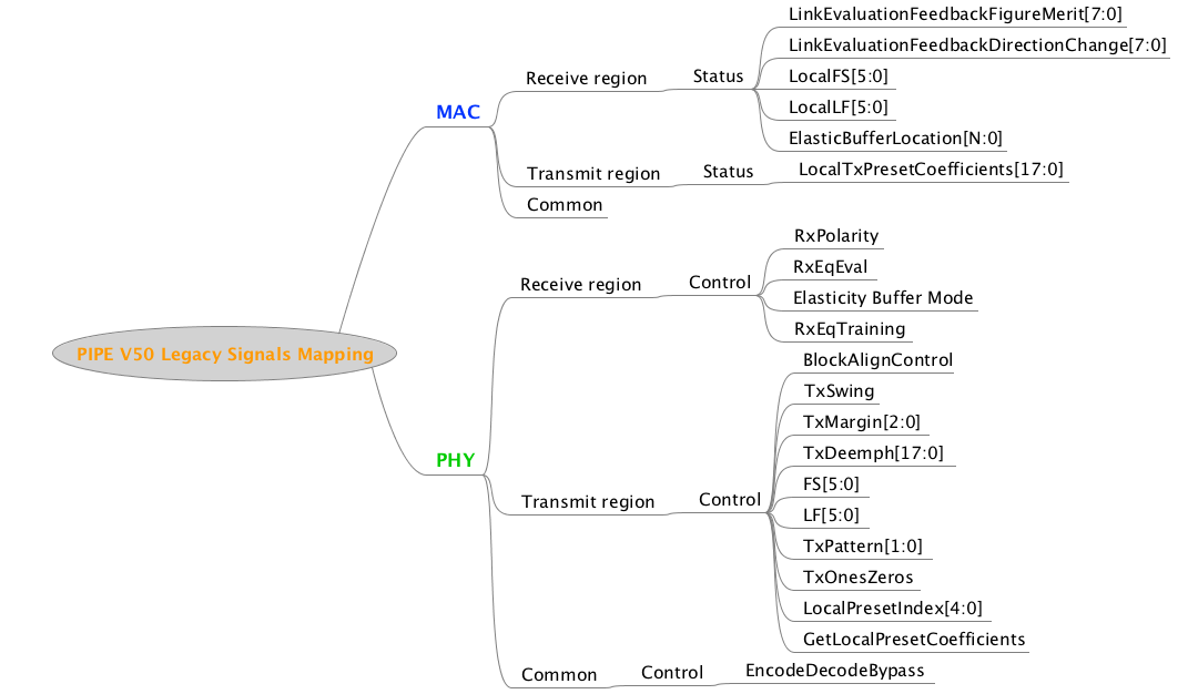
Legacy PIPE signals mapped to message registers
There are 21 legacy PIPE signals mapped to message bus registers. Following is mindmap representation of signal listing and regions to which they are mapped.
More information about exact message bus register mapping can be looked up in the Section 7.0 of the PIPE 5.0 specification.
We hope this helps you get quick glance of what is happening and how it can help you reduce the signal count on the PIPE interface.
This brings in changes to both the MAC and PHY logic. Just the toggle coverage of the PIPE interface is not sufficient to ensure successful integration.
We offer PIPE interface functional coverage model that is comprehensive, configurable and easy to integrate. It can help you reduce the risk of the changes and get the confidence you need in your integration.
[easy_media_download url=”https://www.verifsudha.com/download/1924/” color=”orange_dark” text=”Download brochure” width=”200″]