Tag: functional coverage

  • SystemVerilog: Transition coverage of different object types using cross

    Tudor timisescu also known as the verification gentleman in verification community posted this question on twitter.

    His question was, can we create transition coverage using cross between two different types of objects? He named it as heterogeneous cross.

    His requirement has very useful application in CPU verification to cover transitions of different instructions. For RISC-V (and basically all other ISAs), different instructions have different formats, so you end up with cases where you get such heterogeneous transitions.

    So, let’s jump into understanding the question further. I know it’s not easy to understand it on first impression. So let’s do bit of deep dive into question. Followed by that we will take a look in to one of the proposed solution and scalable automation using the code generation approach.

    Question:

    Can we do heterogeneous cross coverage in SystemVerilog?

    Partial screenshot of the question on twitter.

    Tudor clarifies the question in his own words.

    Heterogeneous cross coverage is cross between two different object types.

    Let me clarify by what I mean with heterogeneous. First, I’m trying to model some more involved form of transition coverage. I imagine the best way to do this is using cross coverage between the current operation and the previous operation.

    Assuming you only have one category of operations, O, each with a set of properties P0, P1, P2, … it’s pretty easy to write this transition coverage. Let the tilde (‘) denote previous. The cross would be between the values of P0, P1, P2, … and P0′, P1′, P2′, …

    If you have two categories of operations, Oa and Ob, each with different sets of properties: Pa0, Pa1, …, Pam for Oa and Pb0, Pb1, …, Pbn (with m and n possibly different), the cross gets a bit more involved.

    If the current operation is of type Oa and the previous is of type Oa, then you want to cover like in the case where all operations are the same (i.e. Pa0, Pa1, …, Pa0′, Pa1′). This also goes for when both are of type Ob.

    If the current operation is of type Oa and the previous is of type Ob, then what you want to cross is something like Pa0, Pa1, Pa2, …, Pb0′, Pb1′, Pb2’, … The complementary case with the operation types switched is analogous to this one.

    I don’t see any way of writing this in #SystemVerilog without having 4 distinct covergroups (one for each type transition).

    Imagine you add a third operation type, Oc, and suddenly you need 9 covergroups you need to write.

    The more you add, the more code you need and it’s all pretty much boilerplate.

    The only thing  that the test bench writer needs to provide are definitions for the cross of all properties of each operation. Since it’s not possible to define covergroup items (coverpoints and crosses) in such a way that they can be reused inside multiple covergroup definitions, the only solution I see is using macros.

    Code generation would be a more robust solution, but that might be more difficult to set up.

    Solution code snippet:

    He was kind enough to provide the solution for it as well. So what was he looking for? He was looking for, is there any easier and scalable ways to solve it?

    Following are the two different data types that we want to cross.

    When you create all 4 possible combinations of transition crosses, it would look as following:

    I thought we could follow the precedence of scientific community and refer the heterogeneous cross as “Tudor cross” for formulating the problem and defining the solution.

    Real life use cases for Tudor cross

    Okay, before we invest our valuable time understanding automation are there any real life use cases?

    Tudor was facing this real problem for project he worked on related to critical pieces of security. For confidentiality reasons he could not provide any more details about it. He was kind enough to share another example where this type of problem would be faced again and hence the solution would be useful.

    In Tudor’s own words, an example from the top of my head (completely unrelated to the one I was working on) where this might be useful is if you have to cover transitions of different instructions. For RISC-V (and basically all other ISAs), different instructions have different formats, so you end up with cases where you get such heterogeneous transitions.

    The same CPU will be executing all of those instructions and you can get into situations that the previous instruction busted something that will cause the current instruction to lock up, which is why you want to at least test all transitions.

    One step even further is if you also add the state of the CPU to the cross. Different parts of the state are relevant to different instructions. It could be that transition a -> b is fine in state Sa0, but is buggy in state Sa1.

    (more…)

  • SystemVerilog : Cross coverage between two different covergroups

    Question:

    Does SystemVerilog support cross coverage between two different covergroups?

    This was one of the question raised on verification academy.

    Following is the code snippet provided by the author to clarify the question.

    Answer:

    SystemVerilog’s covergroup, does not support the cross coverage between two different covergroups as clarified by Dave.

    No, the above code will not compile. The cross a1b1 from covergroup ab1 is used in the different covergroup ab1c1. The cross a1b1 is used in creating cross a1b1c1 in the covergroup ab1c1. Referencing is done in object oriented way ab1.a1b1. Please note the SystemVerilog covergroups are not object oriented. Lack of this support manifests as inability to reuse the cross across covergroups.

    One of the key reasons for not supporting reuse of cross across covergroups is, what if the sampling events across the covergroups are different.

    But what if they are same or it does not matter in specific case of reuse? In that case, why it cannot be reused?

    Before we get in to that real question is, are there sufficient real life use cases for this reuse?

    (more…)

  • Specification to Functional coverage generation

    Introduction

    (Note: As this is a long article, you can download it in pdf format along with USB Power delivery case study. Don’t worry, we don’t ask for email address)

    We were presenting our whitebox functional and statistical coverage generation solution, one of the engineer asked, can it take standard specifications as input and generate the functional coverage from it?

    Figure 1: Specification to functional coverage magic possible?

    I replied “No”. It cannot.

    But then after the presentation, questioned myself as to, why not?

    No, no still not brave enough to parse the standard specifications use natural language processing (NLP) to extract the requirements and generate the functional coverage from it. But we have taken first step in this direction. It’s a baby step. May be some of you might laugh at it.

    We are calling it as high level specification model based functional coverage generation. It has some remarkable advantages. As every time, I felt this is “the” way to write functional coverage from now on

    Idea is very simple. I am sure some of you might have already doing it as well. Capture the specification in form of data structures. Define bunch of APIs to filter, transform, query and traverse the data structures. Combine these executable specifications with our python APIs for SystmVerilog functional coverage generation. Voila, poor man’s specification to functional coverage generation is ready.

    Yes, you need to learn scripting language (python in this case) and re-implement some of the specification information in it. That’s because SystemVerilog by itself does not have necessary firepower to get it all done. Scared? Turned off? No problem. Nothing much is lost. Please stop reading from here and save your time.

    Adventurers and explorers surviving this hard blow please hop on. I am sure you will fall in love with at least one thing during this ride.

    How is this approach different?

    How is this approach different from manually writing coverage model? This is a very important question and was raised by Faisal Haque.

    There are multiple advantages, which we will discuss later in the article. In my view single biggest advantage is making the coverage intent executable by truly connecting the high-level model of specifications to functional coverage. No we are not talking about just putting specification section numbers in coverage plan we are talking about really capturing the specification and using it for generation of functional coverage.

    Let me set the expectations right, this approach will not figure out your intent. The idea is about capturing and preserving human thought process behind the functional coverage creation in executable form. So that it can be easily repeated when things change. That’s all. It’s a start and first step towards specifications to functional coverage generation.

    Typically functional coverage is implemented as set of discrete independent items. The intent and its connection to specifications are weak to non-existent in this type of implementation. Most of the intent gets either left behind in the word of excel plan where it was written or in the form of comments in the code, which cannot execute.

    Making intent executable

    Why capturing intent in executable form is important?

    We respect and value the human intelligence. Why? Is it only for this emotional reason? No. Making human intelligence executable is first step to artificial intelligence.

    Ability to translate the requirements specification into coverage plan is highly dependent on the experiences and depth of specification understanding of the engineer at the moment of writing it. If its not captured in the coverage plan it’s lost. Even the engineer who wrote the functional coverage plan may find it difficult to remember why exactly certain cross was defined after 6 months.

    Now this can become real challenge during the evolution and maintenance of the functional coverage plan as the requirements specifications evolve. Engineer doing incremental updates may not have luxury of the time as the earlier one had. Unless the intent is executable the quality of the functional coverage will degrade over period of time.

    Now if you are doing this design IP for only one chip and after that if you are throwing it away this functional coverage quality degradation may not be such a big concern.

    Let’s understand this little further with example. USB power delivery supports multiple specification revisions. Let’s say, we want to cover all transmitted packets for revision x.

    In manual approach we will discretely list protocol data units valid for revision x.

    For this listing you scan the specifications, identify them and list them. Only way to identify them in code as belonging to revision x is either through covergroup name or comment in the code.

    In the new approach you will be able to operate on all the protocol data units supported by revision x as a unit through APIs. This is much more meaningful to readers and makes your intent executable. As we called out, our idea is to make coverage intent executable to make it adaptable. Let’s contrast both approaches with another example.

    For example, let’s say you want to cover two items:

    • All packet transmitted by device supporting revision 2.0
    • Intermediate reset while all packet transmitted by device supporting revision 2.0

    If you were to write discrete coverage, you would have sampled packet type and listed all the valid packet types of revision 2.0 as bins. Since bins are not reusable in SystemVerilog you would do copy and paste them across these two covergorups.

    Now imagine, if you missed a packet type during initial specification scan or errata containing one more packet type came out later, you need to go back and add this new type at two different places.

    But with this new approach, as soon as you update the specification data structure with new type you are done. All the queries requesting revision x will automatically get updated information. Hence all the functional coverage targeted to revision x will be automatically updated.

    Remember initially it may be easy to spot two places where the change is required. But when you have hundreds of covergroups it will be difficult to reflect the incremental changes to all the discrete covergroups. It will be even more difficult when new engineer has to do the update without sufficient background on the initial implementation.

    In the USB Power delivery case study you will be able to see how to put this concept into action.

    Benefits

    What are the benefits of this approach?

    With high-level specification model based functional coverage the abstraction of thought process of writing coverage moves up and it frees up brain bandwidth to identify more items. This additional brain bandwidth can significantly help improve the quality of functional coverage plan and hence the overall quality of functional verification.

    Benefits of high-level model based functional coverage generation:

    • Intent gets captured in executable form. Makes it easy to maintain, update and review the functional coverage
    • Executable intent makes your coverage truly traceable to specification. Its much better than just including the specification section numbers which leads to more overhead than benefit
    • Its easy to map the coverage from single specification from different components points of view (Ex: USB device or host point of view or PCIe root complex or endpoint or USB Power delivery source or sink point of view) from single specification model
    • Easy to define and control the quality of coverage controlled by the level of details in the coverage required for each feature (Ex: Cover any category, cover all categories or cover all items in each category)
    • Easy to support and maintain multiple versions of the specifications
    • Dynamically switch the view of the coverage implemented based on the parameters to ease the analysis (Ex: Per speed, per revision or for specific mode)

    Architecture

    How to go about building high-level specification model based functional coverage?

    First let’s understand the major components. Following is the block diagram of the high-level specification model based functional coverage. We will briefly describe role and functionality of each of these blocks. This diagram only shows basic building blocks.

    Later we will look at the case studies where we will see these blocks in action making their explanations more clear. It will also guide how to implement these blocks for your project as well.
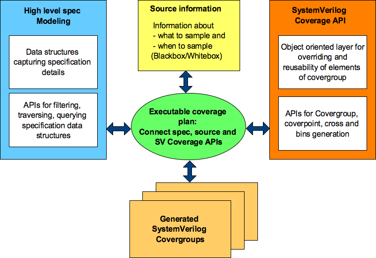
    Figure 2: Block diagram of high-level specification model based functional coverage generation

    Executable coverage plan

    Executable coverage plan is the block that actually hosts all the functional coverage items. It’s coverage plan and its implementation together.

    It does the implementation of functional coverage items by connecting the high-level specification model, source of information and SV coverage APIs. The APIs utilized, specification information accessed and relations of various items utilized preserves the intent in executable form.

    User still specifies the intent of what to cover.

    It won’t read your mind but you will be able to express your thoughts at higher level of abstractions and more closer or specifications and in highly programmable environment that is much more powerful that SystemVerilog alone.

    High-level specification modeling

    This block is combination of set of data structures and APIs.

    Data structures capture high-level information from the specifications. These data structures can be capturing information about properties of different operations, state transition tables representing the state machines, information about timers as to when they start, stop, timeout or graphs capturing various forms of sequences. Idea here is capture the relevant information about the specification that is required for the definition and implementation of the functional coverage. Choose the right form of data structures that fit the purpose. These data structures will vary from domain to domain.

    APIs on the other hand process the data structures to generate different views of the information. APIs can be doing filtering, combinations, permutations or just ease access to the information by hiding the complexity of data structures. There is some level of reuse possible for these APIs across various domains.

    Using these set of data structures and APIs now we are ready to translate the coverage plan to implementation.

    Information source

    Specification data structures may define the structure of operations but to cover it, we need to know how to identify the completion of operation, what is the type operation of operation completed and current values of its properties etc.

    Information source provides the abstraction to bind the specification information to either test bench or design RTL to extract the actual values of these specification structures. This abstraction provides the flexibility to easily switch the source of coverage information.

    Bottom line stores information about sources that are either sampled for information or provides triggers to help decide when to sample.

    SystemVerilog Coverage API in Python

    Why do we need these APIs, why can’t we just directly write it in SystemVerilog itself?

    That’s because SystemVerilog covergroup has some limitations, which prevent the ease of reuse.

    Limitations of SystemVerilog Covergroup

    SystemVerilog functional covergroup construct has some limitations, which prevents its effective reuse. Some of the key limitations are following:

    • Covergroup construct is not completely object oriented. It does not support inheritance. What it means is you cannot write a covergroup in base class and add, update or modify its behavior through derived class. This type of feature is very important when you want to share common functional coverage models across multiple configurations of DUT verified in different test benches and to share the common functional coverage knowledge
    • Without right bins definitions the coverpoints don’t do much useful job. The bins part of the coverpoint construct cannot be reused across multiple coverpoints either within the same covergroup or in different covergroup
    • Key configurations are defined as crosses. In some cases you would like to see different scenarios taking place in all key configurations. But there is no clean way to reuse the crosses across covergroups
    • Transition bin of coverpoints to get hit are expected to complete defined sequence on successive sampling events. There is no [!:$] type of support where the transition at any point is considered as acceptable. This makes transition bin implementation difficult on relaxed sequences

    Coverage API Layering

    At VerifSudha, we have implemented a Python layer that makes the SystemVerilog covergroup construct object oriented and addresses all of the above limitations to make the coverage writing process more productive. Also the power of python language itself opens up lot more configurability and programmability.

    Based on this reusable coverage foundation we have also built many reusable high level coverage models bundled which make the coverage writing easier and faster. Great part is you can build library of high-level coverage models based on best-known verification practices of your organization.

    These APIs allows highly programmable and configurable SystemVerilog functional coverage code generation.

    Fundamental idea behind all these APIs is very simple.

    Figure 3: SV Coverage API layering

    We have implemented these APIs as multiple layers in python.

    Bottom most layer is basic python wrappers through which you can generate the functional coverage along with the support for object orientation. This provides the foundation for building easy to reuse and customize high-level functional coverage models. This is sufficient for the current case study.

    RTL elements coverage models cover various standard RTL logic elements from simple expressions, CDC, interrupts to APPs for the standard RTL element such as FIFOs, arbiters, register interfaces, low power logic, clocks, sidebands.

    Generic functionality coverage models are structured around some of the standard high-level logic structures. For example did interrupt trigger when it was masked for all possible interrupts before aggregation. Some times this type of coverage may not be clear from the code coverage. Some of these are also based on the typical bugs found in different standard logic structures.

    At highest-level are domain specific overage model. For example many high-speed serial IOs have some common problems being solved especially at physical and link layers. These coverage models attempt to model those common features.

    All these coverage models are easy to extend and customize as they are built on object oriented paradigm. That’s the only reason they are useful. If they were not easy to extend and customize they would have been almost useless.

    Implementation

    • Backbone of these APIs is data structure for the SystemVerilog covergroups modeled as list of dictionaries. Each of the covergroup being a dictionary made up of list of coverpoint dictionaries and list of cross dictionaries. Each of the coverpoint and cross dictionaries contain list of bin dictionaries
    • These data structures are combined with simple template design pattern to generate the final coverage code
    • Using layer of APIs on these data structure additional features and limitations of SystemVerilog covergroup are addressed
    • Set of APIs provided to generate the reusable bin types. For example if you want to divide an address range between N equal parts, you can do it through these APIs by just providing the start address, end address and number of ranges
    • There are also bunch of object types representing generic coverage models. By defining the required properties for these object types covergroups can be generated
    • Using python context managers the covegroup modeling is eased off for the user

    Any user defined SystemVerilog code can co-exist with these APIs. This enables easy mix of generated and manually written code where APIs fall short.

    Figure 4: What to expect from APIs

    Structure of user interface

    All the APIs essentially work on the object. Global attributes can be thought of as applicable to entire covergroup. For example if you specified bins at the global level it would apply to all the coverpoints of the covergroup. Not only the information required for coverage generation but also description and tracking information can be stored in the corresponding object.

    This additional information can be back annotated to simulator generated coverage results helping you correlate your high-level python descriptions to final coverage results from regressions easily.

    Also the APIs support mindmaps and Excel file generations to make it easy to visualize the coverage plan for reviews.

    Figure 5: Structure of user interface for objects

    Source information

    Covergroups require what to sample and when to sample.

    This is the block where you capture the sources of information for what to sample and when to sample. It’s based on very simple concept like Verilog macros. All the coverage implementation will use these macros, so that it abstracts the coverage from statically binding to source of the information.

    Later these macros can be initialized with the appropriate source information.

    Snippet 1: Specifying source information

    This flexibility allows using information source from either between the RTL and test bench. Easily be able to switch between them based on need.

    Following code snippets showcase how covergroup implementation for simple read/write and address can be done using either RTL design or test bench transactions.

    Snippet 2: Coverage generated using testbench transaction

    Coverpoints in snippet 2 are sampling the register read write transaction object (reg_rd_wr_tr_obj). Sampling is called on every new transaction

    Snippet 3: Coverage generated using DUT signals

    Coverpoints in snippet 3 are sampling the RTL signals to extract the read/write operation and address. Sampling is called on every new clock qualified by appropriate signals.

    Summary:

    Functional coverage is one of the last lines of defense for verification quality. Being able to repeatedly do a good job and do it productively will have significant impact on your quality of verification.

    Initially it may seem like lot of work, you need to learn a scripting language and learn different techniques of modeling. But pay off will not only for the current project but throughout the lifetime of your project by easing the maintenance and allowing you to deliver the higher quality consistently.

    Download a case study of how this is applied to USB Power delivery protocol layer coverage.

  • When to write to functional coverage plan?

    The question is at what phase of the verification project should one be writing the functional coverage plan?

    Please note that, this question never comes up for the test plan (primarily stimulus plan) and checks or assertion plan. Most of the teams agree that they need to be written at the beginning of the verification project. There is not much of debate there.

    So, why does this question arise only for coverage plan?

    Functional coverage is a metric. Metric implementation by itself does not contribute directly towards completion of task being performed.

    Writing functional coverage will not directly contribute to completion of functional verification. Its correct definition, implementation, analysis and action based on coverage results will contribute to quality of verification completed. Since its multiple hops away from end result and effects are only visible in long term, there is always hesitation to invest in it.

    Anyway let’s go back to our original question and answer it.

    Since our worldview is binary, let’s select two popular answers:

    1. At the beginning of the verification project along with the test plan and checks plan
    2. Somewhere towards later stage of verification project, let’s say when the verification is about 70 – 80 % complete

    Let’s debate on pros and cons of both the answers.

    Here are some arguments on answer #1:

    At the start of project everything is uncovered. So what’s point of having the functional coverage plan? We know our stimulus generation is not up yet so everything is uncovered so why write the functional coverage plan?

    That’s true. From realities of project execution we all know, heat of the project has not picked up yet. So why not use this time to complete the functional coverage plan?

    That seems like reasonable argument.

    Well but we do not have complete knowledge of requirements specifications and nor do we know much about our stimulus as to what we are going to randomize. So what do we capture in the functional coverage plan?

    Okay, let’s say for argument sake even if we write functional coverage plan based on verification requirements. Do we need to start implementation of it as well along with stimulus and checkers? If answer is No, then why write it?

    We all know priorities of features change significantly during the course the execution of project. If we invest in elaborate functional coverage implementation for low priority features the high priority features will suffer. Not all features are made equal. So resource distribution has to be in proportion to priority and importance of the feature. How do we deal with this scenario?

    Let’s pause arguments on this answer and let’s also look at the answer #2. At the end we can try to find the right trade off that helps find satisfactory answers for most of the arguments.

    Here are some arguments on answer #2:

    At about 70% completion of verification, the heat of project execution is reaching close to its peak. The best of your engineering resources are tied to goals focused on closure around stimulus generation and checkers.

    At this point, isn’t it tempting to say code coverage is sufficient? Why invest time in planning and implementing the functional coverage? In the same time we could be writing more tests to close on those last few holes of code coverage.

    Even if we do write the functional coverage plan, are we not already biased towards the stimulus we have already created? Although stimulus coverage is valuable but stimulus coverage alone, can it really help us achieve the desired verification quality for a given design?

    We are already short on time and resources. We don’t have time to write functional coverage plan at this point. Even if we do write a good functional coverage plan magically do we have time to implement the complete functional coverage plan?

    Dizziness

    Enough. That’s enough. Stop these arguments. I knew it. There isn’t any correct answer, so whatever we were doing was correct. You just made me dizzy with all these arguments.

    After hearing all arguments
    After hearing all arguments

    No, wait. Don’t loose the patience.

    Here are some suggestions:

    • Functional coverage plan has to be created along with the test plan and checks plan at the start of the project
    • Functional coverage plan has to be focused from what functional verification needs to deliver to meet the requirements and micro-architecture specifications
    • Functional coverage need not be tightly coupled to stimulus generation. What if your stimulus generation is incorrect or incompletely defined? Its good idea to be focused on overall verification requirements point of view rather than how we generate stimulus to meet those verification requirements. Does it make sense?
    • No need to rush to implement the complete functional coverage plan as soon as its written
    • Tie the functional coverage items to different milestones of the project which even stimulus and checkers have to meet
    • Only implement those relevant for the upcoming milestones. This approach if followed well can help accelerate the code coverage closure at the end. Note that code coverage is not useful in early stages of the project
    • One can keep stimulus and checkers two steps ahead of functional coverage plan implementation in terms of milestones but its important to keep building functional coverage parallel to validate the verification progress to get the best out of it
    • Functional coverage plan’s trackability, implementation and results analysis has to be coupled together along with high flexible and adaptability to keep up with the changing project priorities

    Bottom line we need to understand that the functional coverage is not short-term result oriented activity. We also need to note that its additional work that does not immediately contribute to verification completion. So any inefficiency in the process of writing plan, implementation and its analysis means quality of metric itself will be compromised. That will defeat the whole purpose of having metric in first place. Metric implementation is additional work and additional work has to be always easier in order for it to be done effectively.

    There is not much of benefit of spreading functional coverage thin over many features. If it’s not possible to do justice to all features then develop functional coverage for prioritized sub-set of features.

    Functional coverage: A+ or nothing

    Inspired by the discussion that took place during a  presentation at one of customer premise. Contributions are made by many. Thanks everyone.

    Author: Anand Shirahatti

  • Functional coverage planning: Why we miss critical items?

    World of dynamic simulation based functional verification is not real. Verification architects abstract reality to create the virtual worlds for design under test (DUT) in simulation. Sometimes it reminds me of the architectures created in the movie inception. It’s easy to lose track of what is real and what is not. This leads to critical items being missed in the functional coverage plan. In this article we will look at three point of views to look at feature while doing functional coverage planning to increase chances of discovering those critical scenarios.

    Huh..! In the world of functional verification how do I know, what is real and what is not?

    In simple words if your design under test (DUT) is sensitive to it then its real and if it’s not sensitive to it then it’s not real. Requirements specification generally talks about the complete application. Your DUT may be playing one or few of the roles in it. So it’s important to understand what aspects the application world really matter to your design.

    The virtual nature of the verification makes it difficult to convey the ideas. In such cases some real life analogies come in handy. These should not be stretched too far but should be used to make a focused point clear.

    In this article, we want to talk about how to look at the requirements specifications and micro-architecture details while writing coverage plan. We want to emphasize the point micro-architecture details are equally important for functional coverage plan. Often verification teams ignore these. It affects the verification quality. Let’s look at the analogy to specifically understand why micro-architecture details matter to verification engineer? How much should he know? Let’s understand this with analogy.

    Analogy

    Let’s say patient approaches orthopedic surgeon to get treatment for severe back pain. Orthopedic surgeon prescribes some strong painkillers, is it end of his duty? Most painkiller tablets take toll on stomach and liver health. Some can even trigger gastric ulcers. What should orthopedic surgeon do? Should he just remain silent? Should he refer him to gastroenterologist? Should he include additional medications to take care of these side effects? In order to include additional medications to take care of side effects how far should orthopedic surgeon get into field of gastroenterology? Reflect on these based on real life experiences. If you are still young then go talk to some seniors.

    The same dilemma and questions arise when doing functional coverage planning. Functional coverage planning cannot ignore the micro-architecture. Why?

    When the requirements specifications are translated to micro-architecture, it introduces its own side effects. Some of these can be undesirable. If we choose to ignore it, we risk those undesirable side effects showing up as bugs.

    Dilemma

    Well we can push it to designers saying that they are the ones responsible for it. While it’s true to some extent but only when designer’s care for verification and verification cares for design first pass silicon dreams can come true. We are not saying verification engineers should be familiar with all intricacies of the design but the basic control and data flow understanding cannot be escaped.

    Functional coverage planning: 3 points of view

    All the major features have to be thought out from three points of views while defining functional coverage. There can be certain level of redundancy across these but this redundancy is essential for the quality.

    Those three points of view are:

    1. Requirements specification point of view
    2. Micro-architecture point of view
    3. Intersection between requirements and micro-architecture point of view

    For each of these how deep to go is dependent on the sensitivity of the design to the stimulus being thought out.

    Let’s take an example to make this clearer.

    Application of 3 points of view

    Communication protocols often rely on timers to figure out the lost messages or unresponsive peers.

    Let’s build simple communication protocol. Let’ say it has 3 different types of request messages (M1, M2, M3) and single acknowledgement (ACK) signaling successful reception. To keep it simple unless acknowledged the next request is not sent out. A timer (ack_timer) is defined to takes care of lost acknowledgements. Range of timer duration is programmable from 1ms to 3ms.

    In micro-architecture this is implemented with simple counter that is started when any of requests (M1, M2, M3) is sent to peer and stopped when the acknowledgement (ACK) is received from peer. If the acknowledgement is not received within the pre-defined delay a timeout is signaled for action.

    So now how do we cover this feature? Let’s think through from all three points of view and see what benefits do each of these bring out.

    Requirements specification point of view:

    This is the simplest and most straightforward among the three. Coverage items would be:

    • Cover successful ACK reception for all three message types
    • Cover the timeout for all three message types
    • Cover the timeout value for Min(1 ms), Max(3 ms) and middle value( 2ms)

    Don’t scroll down or look down.

    Can you think of any more cases? Make a mental note; if they are not listed in below sections, post them as comments for discussion. Please do.

    Micro-architecture point of view:

    Timer start condition does not care about which message type started it. All the message types are same from the timer point of view. From timer logic implementation point of view, timeout due to any one message type is sufficient.

    Does it mean we don’t need to cover timeout due to different message types?

    It’s still relevant to cover these from requirements specification point of view. Remember through verification we are proving that timeout functionality will work as defined by specification. Which means, we need to prove that it will work for all three-message types.

    Micro-architecture however has its own challenges.

    • Timeout needs to covered multiple times to ensure the mechanism of timer reloading takes place correctly again after timeout
    • System reset in the middle of timer running followed by timeout during operation needs to be covered. It ensures that system reset in middle of operation does reset the timer logic cleanly without any side effects (difference between power on reset vs. reset in middle)
    • If the timer can be run on different clock sources it needs to be covered to ensure it can generate right delays and function correctly with different clock sources

    Requirement specification may not care about these but these are important from micro-architecture or implementation point of view.

    Now let’s look at intersection.

    Intersection between requirements and micro-architecture point of view

    This is the most interesting area. Bugs love this area. They love it because of intersection, shadow of one falls on another creating dark spot. Dark spots are ideal places for the bugs. Don’t believe me? Let’s illuminate and see if we find one.

    Generally synchronous designs have weakness around +/- 1 clock cycle around key events. Designers often have to juggle lot of conditions so they often use some delayed variants of some key signals to meet some goals.

    Micro-architecture timeout event intersecting with external message reception event is interesting area. But requirements specification cares for acknowledgement arriving within timeout duration or after timeout duration.

    What happens when acknowledgement arrives in following timing alignments?

    • Acknowledgement arrives just 1 clock before timeout
    • Acknowledgement arrives at the same clock as timeout
    • Acknowledgement arrives just 1 clock after timeout

    This is area of intersection between the micro-architecture and requirement specification leads to interesting scenarios. Some might call these as corner cases but if we can figure out through systematic thought process, shouldn’t it be done to the best possible extent?

    Should these cases of timing alignment be covered for all message types? Its not required because we know that timer logic is not sensitive to message types.

    Another interesting question is why not merge the point views #1 and #2? Answer is thought process has to be focused on one aspect at a time, enumerate it fully and then go to other aspect enumerate it fully then go figure out the intersection between them. Any shortcuts taken here can lead to scenarios being missed.

    Closure

    This type of intent focused step-by-step process enhances the quality of functional coverage plans and eases the maintenance when features are updated.

    Some of you might be thinking, it will take long time and we have schedule pressure and lack of resources. Let’s not forget quality is remembered long after the price is forgotten.

  • Functional coverage for Micro-architecture – Why?

    Functional coverage plan in order to be effective has to take into consideration two specifications. They are:

    In principle verification teams readily agrees to above. But when it comes to defining the coverage plan it does not reflect.

    In general functional coverage itself receives less attention. On the top of that among the above two, requirements specifications coverage ends up getting lion share. Micro-architecture implementation coverage gets a very little attention or almost ignored.

    For some it may look like an issue out of nowhere. They may argue, as long as requirements specifications are covered through functional coverage, micro-architecture coverage should be taken care by code coverage.

    Why do we need functional coverage for micro-architecture?

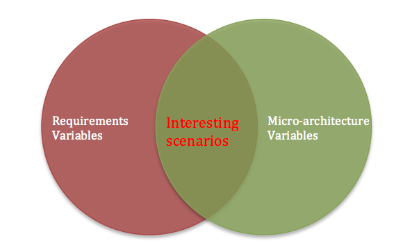
    We need functional coverage for micro-architecture specifications as well because interesting things happen at the intersection of requirements specification variables and micro-architecture implementation variables.


    Requirements and Implementation variable intersection
    Requirement and Implementation variable intersection

    Many of the tough bugs are hidden at this intersection and are caught very late in verification flow or worse in silicon due to above thought process.

    How? Let’s look at some examples.

    Example#1

    Design with pipeline, combinations of states across stages pipelines is an important coverage metric for the quality of stimulus. Just the interface level stimulus of all types of inputs, will not be able to provide idea about whether all interesting states combinations are exercised for the pipeline.

    Example#2

    Design with series of FIFOs in the data paths, combinations of FIFO back pressures taking place at different points and with different combinations is interesting to cover. Don’t wait for stimulus delays to uncover it.

    Example#3

    Design implementing scatter gather lists for communication protocol, not only the random size of the packets are important but the packet sizes colliding with the internal buffer allocation sizes is very important.

    For example let’s say standard communication protocol allows maximum payload up to 1 KB. Internally design is managing buffers in multiples of 256 bytes then multiple packets of size less than or equal to 256 bytes or multiples of 256 bytes are especially interesting to this implementation.

    Note here from protocol point of view this scenario is of same importance as any random combinations of the sizes. If the design changes the buffer management to 512 bytes the interesting packet size combinations changes again. One can argue constrained random will hit it. Sure it may but probabilistic nature can make it miss as well. If it misses its expensive miss.

    Covering and bit of tuning constraints based on the internal micro-architecture can go long way in helping find issues faster. Note this does not mean not to exercise other sizes but pay attention to sensitive sizes because there is higher likelihood of hard issues hiding there.

    This interesting intersection is mine of bugs but often ignored in the functional coverage plan due to following three myths.

    Myth#1: Verification engineers should not look into design

    There is this big taboo that verification engineers should not look into the design. Idea behind this age-old myth is to prevent verification engineers from limiting the scope of verification or getting biased from design.

    This forces verification engineers to focus only on the requirements specification and ignore the micro-architecture details. But when tests fail as part of debug process they would look in to the design anyway.

    Myth#2: Code coverage is sufficient

    Many would say code coverage is sufficient for covering micro-architecture specification. It does but it does it only partially.

    Remember code coverage is limited as it does not have notion of time. So concurrent occurrence and sequences will not be addressed by the code coverage. If you agree above examples are interesting then think is code coverage addresses them.

    Myth#3: Assertion coverage can do the trick

    Many designers add assertions into the design for assumptions. Some may argue covering these is sufficient to cover micro-architecture details. But note that if intent assertion is to check for assumption then it’s not same as functional coverage for implementation.

    For example let’s say we have simple request and acknowledgement interface between the internal blocks of design. Let’s say acknowledgement is expected within 100 clock cycles after request assertion. Now designer may place assertion capturing this requirement. Sure, assertion will fire error if acknowledgement doesn’t show up within 100 clock cycles.

    But does it cover different timings of acknowledgement coming in? No, it just means it has come within 100 cycles. It does not tell if acknowledgement has come immediately after request or in 2-30 clock cycles range or 30-60 clock cycles range or 61-90 clock cycles range or 91-99 clock cycles range and exactly at 100 clock cycles.

    However there are always exceptions, there are few designers who do add explicit micro-architecture functional coverage for their RTL code. Even there they restrict scope to their RTL sub-block. The holistic view of complete micro-architecture is still missed here.

    Micro-architecture functional coverage: No man’s land

    Simple question, who should take care of adding the functional coverage requirements of the micro-architecture to coverage plan?

    Verification engineers would argue we lack understanding of the internals of the design. Design engineers lack understanding of functional coverage and test bench.

    All this leads to micro-architecture functional coverage falling in no man’s land. Due to lack clarity on responsibility of implementation of micro-architecture functional coverage it’s often missed or implemented to very minimal extent.

    This leads to hard to fix bugs only discovered in silicon like Pentium FDIV bug. Companies end up paying heavy price. Risk of this could have minimized significantly with the help of micro-architecture functional coverage.

    Both verification and design engineers can easily generate it quickly using library of built-in coverage models from our tool curiosity.

  • PCI Express PIPE interface functional coverage

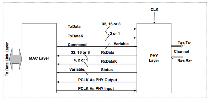
    What started off, as “PHY Interface for the PCI Express Architecture” was soon promoted to “PHY interface for the PCI Express, SATA and USB3.1 and SATA”. It was primarily designed to ease the integration of digital MAC Layer with the mixed signal PHY.

    PIPE Interface for MAC and PHY Integration
    PIPE Interface for MAC and PHY Integration

    Today as of October 2017 latest publicly available PIPE specification is version 4.4.1. All the waveforms and pictures are sourced from this specification. If we go back 10 years in time to 2007, PIPE specification was at version 2.0.

    Version 2.0 was for PCI express only. It had only 5 contributors and 38 pages. Whereas version 4.4.1 has 32 contributors and 114 pages. It supports not only PCI express, SATA and USB3.1 as well. Version 4.4.1 has had 5x growth in contributors and 3x growth in number of pages compared to version 2.0.

    It’s also indication of rise in complexity of PCI express as well. PCI express has been one of the leading high-speed serial interface technologies. Hence there are multiple IP companies helping with the adoption of the technology. Apart from Big 3 there are also many vendors who provide the PCI express IP solutions. Some provide both the MAC layer and PHY while other provide one of them and partner with complementary vendors to provide the complete solution.

    PCI express even at the PIPE interface level has quite a bit of configurability. This comes out in terms of width, rate and PCLK frequencies. Also some companies do make certain level of customization to this interface to support custom features.

    To accelerate the simulation speed many verification environments for the PCI express controllers support both the PIPE and serial interface. Parallel PIPE interface runs faster than serial PHY interface. PHY would also require mixed signal simulations as well to verify the analog parts in it.

    Considering the complexity there is lot of focus on verifying the MAC layer and PHY layer independently. This creates challenge as to what to verify when they are put together. Obviously it’s not practical to run again all the PHY and MAC layers tests put together on integrated design.

    Vendors would make attempt to verify all configurations but do all the configurations get equal attention is something difficult to assess.

    When the PCI express IPs are bought from the 3rd party vendors it’s a challenge as to what to cover for integration verification.

    PIPE interface coverage can be one of the very useful metric to decide on what tests to run for integration verification. This becomes even more important if the digital controller and PHY are sourced from different vendors.

    One can say simple toggle coverage of all the PIPE signals should be sufficient to ensure the correct integration. Yes this is necessary but not sufficient.

    Following are some of the reasons why just toggle coverage will not suffice.

    • Toggling in all the speeds

    Some of the signals of PIPE interface are used only in specific speeds of operation. So it’s important to check for the toggle in appropriate speed. Simple toggle coverage will not indicate in which speed the signals toggled.

    Some examples are link equalization signals of the command interface signals such as RxEqEval, RxEqInProgress or 130b block related signals such TxSyncHeader, RxSyncHeader are only applicable for the Gen3 (8 GT/s ) or Gen4(16 GT/s) speeds etc.

    • Transition or sequence of operations

    Some of the signals instead of just individual toggle coverage require transition or sequence of events coverage to confirm the correct integration.

    Some examples are six legal power state transitions, receiver detection sequence, transmitter beacon sequence etc.

    • Variation of timing

    Some of the signals can be de-asserted at different points of time. There can be multiple de-assertion or assertion points that are valid. Based on the design it’s important to confirm the possible timing variations are covered.

    For example following waveform RxEqEval can de-assert along with PhyStatus de-assertion or later.

    • Concurrency of interfaces

    PIPE provides 5 concurrent interfaces, transmit data interface, receive data interface, command interface, status interface and message bus interface.

    Simple concurrency like transmit and receive taking place at same time cannot be indicated by the toggle coverage.

    • Combinations

    Some signals, which are vectors, may not have all the values defined to achieve the toggle coverage.

    LocalPresetIndex[4:0] for example has only 21/32 valid values. Here toggle can indicate connection but whether both the digital controller and PHY can handle all combinations of values together is not confirmed.

    Also behavior of some key signals in different states needs to be confirmed to ensure the correct integration. TxDeemph[17:0] values will have to be covered based on rate of operation as toggle of all bits may not be meaningful.

    • Multiple lanes

    PIPE interface allows certain signals to be shared across multiple lanes. In multi lane case combinations of the lanes active coverage becomes important.

    • Multiple times

    Some of events or sequences are not sufficient just covered once. Why?

    For example in the following waveforms the InvalidRequest must de-assert at the next assertion of RxEqEval. So multiple RxEqEval are required to complete the sequence of the InvalidRequest

    Putting all these together results in functional coverage plan containing 88 cover items.

    PCIe PIPE functional coverage plan pivot table

    With our configurable coverage model we can easily customize and integrate all the above covergroups in your verification environment.

    We offer service to tell you where your verification stands from PIPE integration coverage point of view.

  • Verification plan debate – Part IV

    Continued from: Verification debate Part III

    Ananta could not sleep although he was really tired. His body was tired but his mind was still racing at full throttle. He started reflecting.

    He was pondering on how sheriff was able to get his hands on escaped convict so quickly? How it prevented breach of the confidential informers data which could have lead to further crime.

    Action of patrol teams in motion, teams that were stationed at sensitive points, investigation and emergency response handled this case had made deep impression on Ananta’s mind. Their contribution was evident and appreciated.

    However the informers who played equally important role in the whole process almost went unnoticed. This was one of the missing pieces of puzzles he felt. He continued to reflect on this fact.

    What would be informers in the context of functional verification? He had a sudden flash of insight. He finally figured out it was coverage plan. Coverage is like your informers network. You need omnipresence of coverage by combining both the code and functional coverage.

    With coverage we gain clarity as to where we need target our stimulus and checks. Without it we are blind.

    He thought is it just me who had ignored the coverage plan or rest of world is doing the same?

    He thought of doing a quick check. It was already late in night.

    He messaged his friend Achyuta, Are you awake? Hey what’s up Ananta came back a quick reply.

    Ananta replied can you send me number of page views on the blogs of verification planning that you had pointed me earlier at once if convenient. If inconvenient, send all the same.

    In next 10 minutes following were the number sent out by Achyuta. All these blogs got online almost around same timelines. Being read by readers over a year now. Here are the page views statistics:

    From August 2016 – September 2017 duration pageviews:

    Page tile Page Views
    Test plan 799
    Checks or assertion plan 354
    Coverage plan 271

    Test plan has 200% more views compared to checks or assertion plan. Test plan also has close to 300 % more views compare to coverage plan.

    This data makes it clear thought Ananta. He smiled, I am not alone.

    Coverage plan is given least importance among three. Remember coverage plan is doing the job of informer. At times you can raid and even capture criminals without informers but you would lack the accuracy and speed of response.

    With all three verification plans getting right level of attention, we also should be able to bring down the bugs rate.

    Ananta got excited and he had to share these realizations with Achyuta. It’s the debates with him that had aroused his curiosity in first place so he had share it with him. He called him up. He knew it would interest him as well.

    Achyuta looks like finally I understand the riddle of verification plan now. He shared his findings connecting all the dots in single breath.

    We are excessively focusing on stimulus. Our focus on checks or assertion is lacking. Our focus on the functional coverage is even lower. That explains bugs rate. We are working hard and we are making our machine farms work even harder by running regression with thousands of tests. We are not doing it effectively. What is happening in regression is staying in regression. We need more transparency into effectiveness of our regressions.

    Many times, our best players are fighting hard on wrong battles. Our ad hoc approach is taking toll on them. Let’s accept it we only have handful of A+ players. We need to invest part of their bandwidth on strategic tasks of writing and maintaining the verification plan.

    Verification plan is not something that is written once at beginning of project and finished for good. It evolves. This is a plan to cope with the changes not a line set in stone. We are innovating and by definition it means things will change and evolve. No one knows requirements completely from start. We have to deal with ambiguity. Our only chance is we have verification plan that can evolve and adapt to these changes. We need to provide the equal importance to all three plans.

    If we do get these three plans right then these are three strings that can be pulled to control the entire execution of the functional verification. It can greatly streamline execution and enable us to adapt to changing priorities without dropping any balls on the floor. It will also bring in a good level predictability and ease to make informed decisions to on what features to cut down to meet schedules.

    Bravo Bravo shouted Achyuta being unable to control his excitation.

    This woke up his wife who looked straight at him with her red eyes in half asleep.

    Achyuta’s heart skipped a beat. There was moment of silence. Ananta was quick to sense it.

    He said, I am coming back this weekend anyway so let’s catch up at our usual coffee place we have lot more to talk. Good night, I mean Good morning.

    See you soon…


  • Pentium FDIV bug and curious engineer

    According to wikipedia Pentium FDIV bug affects the floating point unit(FPU) of the early intel Pentium processors. Because of this bug incorrect floating point results were returned. In December 1994, Intel recalled defective processors. In January 1995, Intel announced “a pre-tax charge of 475 Million against earnings. Total cost associated with the replacements of the flawed processors.

    What went wrong here?

    According byte.com web page archive, Intel wanted to boost the execution of their floating-point unit. To do that they moved from its traditional shift-and-subtract division algorithm to new method called SRT algorithm. SRT algorithm uses a lookup table. Pentium’s SRT  lookup table implementation is matrix of 2048 cells. Only 1066 of these cells actually contained the valid values. Due to issue in script loading the lookup table 5/1066 entries were not programmed with valid values.

    SRT algorithm is recursive. This bug leads to corruption only with certain pairs of divisors and numerators. The “buggy pairs” are identified. They always lead to corruption. At its worst, the error can rise as high as the fourth significant digit of decimal number. Chances of this happening randomly, is about 1 in 360 billion. Usually the error appears around the 9th or 10th decimal digit. The chances of this happening randomly, is about 1 in 9 billion.

    Isn’t randomization on inputs sufficient?

    Here you can see even if we had constrained random generation on divisor and numerators how low is probability of hitting the buggy pair. Even if we create the functional coverage on the inputs how low is probability that we would specifically write coverpoints for the buggy pair.

    Of-course now we have formal methods to prove correctness of such computationally intensive blocks.

    We are already convinced that constrained random hitting on this buggy pair has very low probability. Hence even if it hits this case it may take long wall clock time. Pure floating-point arithmetic verification approach alone is not sufficient.

    For a moment if you think what could have helped maximize the probability of finding this issue in traditional simulation based verification?

    Simulation world is always time limited. We cannot do exhaustive verification of everything. Even a simple 32-bit counter exhaustive verification would mean 2 ^ 32 = 4G of state space. That’s where the judgment of the verification engineers plays major role as to what to abstract and what to focus.

    Story of curious engineer

    Let’s say a curious verification engineer like you looked inside the implementation. He tried to identify the major blocks of design and spotted the lookup table. His mind suddenly flashed insight  floating-point inputs must use all valid entries of the lookup table. This is one more critical dimension for the quality of the input stimulus.

    Let’s say he thought of checking that by writing functional coverage on input address of the lookup table. He thought of adding a bin per each valid cell of matrix.

    This could have helped maximize the probability of catching this issue. There is a notion that verification engineers should not look into design as it can bias their thinking. While the intent is good but let’s not forget we are verifying this specific implementation of requirements. Some level of balancing act is required. It cannot be applied in purity.

    (more…)

  • Functional coverage – Value proposition

    Functional coverage complements the code coverage by addressing its inherent limitations. This blog will help you understand what is the key value proposition of the functional coverage. This in turn will help you achieve the maximum impact from it.

    Functional verification has to address verification requirements made up of both requirements specifications and implementation.

    Functional coverage’s primary purpose is finding out has the functional verification done its job well. The means used for functional verification to achieve the goal doesn’t matter in this context. It can achieve it with all directed tests or use constrained random or use emulation.

    When the functional verification relies on the constrained random approach functional coverage helps in finding out the effectiveness of constraints. It helps in finding out the constraints are correct and they aren’t over constraining. But this aspect of the functional coverage has become so popular that the primary purpose of it has become overshadowed.

    Functional coverage focuses on following three with possible overlap between each other to figure out whether the functional verification objectives are met:

    • Randomization or stimulus coverage
    • Requirements coverage
    • Implementation coverage

    In the following sections we will briefly discuss what each of these mean

    Randomization or stimulus functional coverage

    Uncertainness of constrained random environments is both boon and bane. Bane part is addressed with the functional coverage. It helps provide the certainty that randomization has indeed hit the important values that we really care for.

    At a very basic level it starts with ensuring each of the randomized values are covering the their entire range of values possible. This is not the end of it.

    Functional coverage’s primary value for the constrained random environments is to determine its effectiveness in randomization. Functional coverage quantifies the effectiveness of randomization. This does not directly say anything about effectiveness or completeness of the functional verification. This just means we have enabler that can help achieve the functional verification goals.

    It’s the requirements and implementation coverage that really measures the effectiveness and completeness of the functional verification.

    Requirements functional coverage

    Requirements specification view of functional verification is looking at design from the end application point of view.

    Broadly it looks at whether test bench is capable of covering the required scope of verification from application scenarios point of view. That includes:

    • All key atomic scenarios in all key configurations
    • Concurrency or decoupling between features
    • Application scenario coverage
      • Software type of interactions:
        • Like polling versus interrupt driven
        • Error recovery sequences
        • Virtualizations and security
      • Various types of traffic patterns
      • Real life interesting scenarios like:
        • Reset in middle of traffic
        • Zero length transfer for achieving something
        • Various types of low power scenarios with different entry and exit conditions
        • Various real life delays(can be scaled proportionately)

    Bottom line is requirement specification functional coverage should be able to convince someone who understands requirements that design will work without knowing anything about implementation. This is one the primary value that functional coverage brings over the code coverage.

    Implementation functional coverage

    Implementation related functional coverage is highly under focused area. But remember it’s equally important one. Many verification engineers will fall in trap that code coverage will take care of it. Which is only partially true.

    The implementation means the micro-architecture, clocking, reset, pad or any other analog components interface related aspects.

    Micro-architecture details to be covered include internal FIFOs becoming full and empty multiple times, arbiters experiencing various scenarios, concurrency of events, multi-threaded implementation, pipelines experiencing various scenarios etc.

    Clocking coverage is whether all the specification defined clock frequency ranges are covered, for multiple clock domains key relations between the two clocks, special requirements such as spread spectrum, clock gating etc.

    For resets whether external asynchronous resets at all the key states of any internal state machines. For multi-client or multi-channel where they are expected to operate independently if one is in reset whether other can make progress etc.

    Pads and analog blocks interface coverage is very critical. Making sure all the possible interactions is exercised whether effects can be seen or not in the simulation is still important.

    Combination of the white box and black box functional coverage addresses both of the above.