Blog

  • Register verification : Why are we still missing the issues?

    RISC-V open virtual platform simulator quoted “Silicon without software is just a sand”. Well, it’s true. Isn’t it?

    For many design IPs, the programming interface to the software is through a set of registers. The registers contained by design IP can be broadly divided into 3 categories.

    • Information registers: Set of registers that provides the static information about the design IP. Some examples are vendor ID or revision information or capabilities of the design
    • Control registers: Set of registers that allow controlling the behavior or features of the design IPs. These are called control registers. Some examples include enable/disable controls, thresholds, timeout values etc.
    • Status registers: Set of registers that provides the ability to report various events. Some examples are interrupt status, error status, link operational status, faults etc.

    The software uses the “information registers” for the initial discovery of the design IP. There on programs the subset of control registers in a specific order to make the design IP ready for the operation. During the operation, status registers provide the ability for the software to figure out if the design IP is performing the operations as expected or does it need some attention.

    Register verification

    From verification point of view we need to look at it from two points of view. They are:

    • Micro-architecture point of view
    • Requirement specification point of view

    Micro-architecture point of view focuses on the correctness of the implementation of the register structure. Which can be described some of the following items:

    • Each register bit properties implemented as read-only, read-write, write to clear, read to clear or write-1-clear type of implementation
    • Is the entire register address space accessible for both read and write
    • If there are any byte enables used are they working correctly
    • All possible read and write sequences operational
    • Protected register behavior is as expected

    From requirements point of view focuses is on the correctness of the functionality provided by the register. Which can be described some of the following items:

    • Whether the power on reset value matches the expected value defined by the specification
    • For all the control registers whether the programmed values are having the desired effect
    • When the events corresponding to different status register updates are taking place, whether they are reflecting it correctly
    • Any status registers whose values needs to be retained through the reset cycling
    • Any registers that needs to be restored to proper values through power cycling are they taking place correctly

    Micro-architecture implementation correctness is typically verified by the set of the generated tests. Typically a single automation addresses the RTL registers generation, UVM register abstraction layer generation and associated set of test generation. These automations also tend to generate the documentations about registers, which can serve as programming guides for both verification and software engineering teams.

    Functional correctness of the registers is the more challenging area. Information category of registers is typically covered by the initial values checking tests. Control and status register functional correctness is spread out across various tests. Although some tests may explicitly verify the register functional correctness, but many tests that cover register functional correctness are not really verifying only that. They are focusing on higher-level operational correctness, in doing so, they utilize the control and status registers. Hence they verify them indirectly.

    In spite of all this verification effort, register blocks still will end up having some issues, which are found late in verification cycles or during silicon bring up.

    Why we are still missing the issues?

    Register functionality evolves throughout the project execution. Typical changes are in the form of additions, relocations, extensions, update to definitions of existing registers and compacting the register space by removing some registers.

    Automations associated with registers generation ease the process of any changes. At the same times, sometimes layers of automations can make the process of review difficult or give a false sense of positive security that all changes are being verified by automatically generated tests. The key point is automation is only as good as the high-level register specification provided as input. If there are mistakes in the input, sometimes automations  can  mask them.

    Since the register verification is spread out across automated tests, register specific tests and other features testing, its difficult to pin-point what gets verified and to what extent.

    What can we do about it?

    First is traditional form of review. This can help catch many of the issues. But considering the total number of registers and their dynamic nature it’s difficult to do this review thoroughly and iteratively.

    We need to aid the process of reviews. We need to open up the verification to questioning by designers and architects. This can be effectively done when there are high-level data about the verification done on the registers.

    We have built a register analytics app that can provide various insights about your register verification in the simulation.

    One of the capabilities register app helped catch issues of dynamically reprogrammed registers. There are subsets of control registers that can be programmed dynamically multiple times during the operations. As the register specification kept on changing the transition coverage on a specific register which was expected to be dynamically programmed was not added.

    Our register analytics app provided the data regarding which registers were dynamically reprogrammed, how many times they were reprogrammed and what unique value transitions were seen. It was made available as a spreadsheet. One could quickly filter the columns of registers that were not dynamically programmed. This enabled questioning of why certain registers were not dynamically reprogrammed? This enabled catching certain dynamically re-programmable registers, which were not reprogrammed. When they were dynamically reprogrammed some them even lead to the discovery of additional issues.

    We have many more micro-architecture stimulus coverage analytics apps that can quickly provide you the useful insights about your stimulus. The data is available both at per test as well as aggregated across the complete regression. Information from third party tools can additionally provide some level or redundancy to verification efforts catching any hidden issues in the automations already used.

    If you are busy, we do offer services to set up our analytics flow containing both functional and statistical coverage, run your test suites and share the insights that can help you catch the critical bugs and improve your verification quality.

  • SystemVerilog: Transition coverage of different object types using cross

    Tudor timisescu also known as the verification gentleman in verification community posted this question on twitter.

    His question was, can we create transition coverage using cross between two different types of objects? He named it as heterogeneous cross.

    His requirement has very useful application in CPU verification to cover transitions of different instructions. For RISC-V (and basically all other ISAs), different instructions have different formats, so you end up with cases where you get such heterogeneous transitions.

    So, let’s jump into understanding the question further. I know it’s not easy to understand it on first impression. So let’s do bit of deep dive into question. Followed by that we will take a look in to one of the proposed solution and scalable automation using the code generation approach.

    Question:

    Can we do heterogeneous cross coverage in SystemVerilog?

    Partial screenshot of the question on twitter.

    Tudor clarifies the question in his own words.

    Heterogeneous cross coverage is cross between two different object types.

    Let me clarify by what I mean with heterogeneous. First, I’m trying to model some more involved form of transition coverage. I imagine the best way to do this is using cross coverage between the current operation and the previous operation.

    Assuming you only have one category of operations, O, each with a set of properties P0, P1, P2, … it’s pretty easy to write this transition coverage. Let the tilde (‘) denote previous. The cross would be between the values of P0, P1, P2, … and P0′, P1′, P2′, …

    If you have two categories of operations, Oa and Ob, each with different sets of properties: Pa0, Pa1, …, Pam for Oa and Pb0, Pb1, …, Pbn (with m and n possibly different), the cross gets a bit more involved.

    If the current operation is of type Oa and the previous is of type Oa, then you want to cover like in the case where all operations are the same (i.e. Pa0, Pa1, …, Pa0′, Pa1′). This also goes for when both are of type Ob.

    If the current operation is of type Oa and the previous is of type Ob, then what you want to cross is something like Pa0, Pa1, Pa2, …, Pb0′, Pb1′, Pb2’, … The complementary case with the operation types switched is analogous to this one.

    I don’t see any way of writing this in #SystemVerilog without having 4 distinct covergroups (one for each type transition).

    Imagine you add a third operation type, Oc, and suddenly you need 9 covergroups you need to write.

    The more you add, the more code you need and it’s all pretty much boilerplate.

    The only thing  that the test bench writer needs to provide are definitions for the cross of all properties of each operation. Since it’s not possible to define covergroup items (coverpoints and crosses) in such a way that they can be reused inside multiple covergroup definitions, the only solution I see is using macros.

    Code generation would be a more robust solution, but that might be more difficult to set up.

    Solution code snippet:

    He was kind enough to provide the solution for it as well. So what was he looking for? He was looking for, is there any easier and scalable ways to solve it?

    Following are the two different data types that we want to cross.

    When you create all 4 possible combinations of transition crosses, it would look as following:

    I thought we could follow the precedence of scientific community and refer the heterogeneous cross as “Tudor cross” for formulating the problem and defining the solution.

    Real life use cases for Tudor cross

    Okay, before we invest our valuable time understanding automation are there any real life use cases?

    Tudor was facing this real problem for project he worked on related to critical pieces of security. For confidentiality reasons he could not provide any more details about it. He was kind enough to share another example where this type of problem would be faced again and hence the solution would be useful.

    In Tudor’s own words, an example from the top of my head (completely unrelated to the one I was working on) where this might be useful is if you have to cover transitions of different instructions. For RISC-V (and basically all other ISAs), different instructions have different formats, so you end up with cases where you get such heterogeneous transitions.

    The same CPU will be executing all of those instructions and you can get into situations that the previous instruction busted something that will cause the current instruction to lock up, which is why you want to at least test all transitions.

    One step even further is if you also add the state of the CPU to the cross. Different parts of the state are relevant to different instructions. It could be that transition a -> b is fine in state Sa0, but is buggy in state Sa1.

    (more…)

  • SystemVerilog : Cross coverage between two different covergroups

    Question:

    Does SystemVerilog support cross coverage between two different covergroups?

    This was one of the question raised on verification academy.

    Following is the code snippet provided by the author to clarify the question.

    Answer:

    SystemVerilog’s covergroup, does not support the cross coverage between two different covergroups as clarified by Dave.

    No, the above code will not compile. The cross a1b1 from covergroup ab1 is used in the different covergroup ab1c1. The cross a1b1 is used in creating cross a1b1c1 in the covergroup ab1c1. Referencing is done in object oriented way ab1.a1b1. Please note the SystemVerilog covergroups are not object oriented. Lack of this support manifests as inability to reuse the cross across covergroups.

    One of the key reasons for not supporting reuse of cross across covergroups is, what if the sampling events across the covergroups are different.

    But what if they are same or it does not matter in specific case of reuse? In that case, why it cannot be reused?

    Before we get in to that real question is, are there sufficient real life use cases for this reuse?

    (more…)

  • Verification analyst : Missing piece in puzzle of gaps in verification metrics

    Industry leaders from ARM, Intel, Nvidia, AMD are saying there are gaps in verification metrics. ANN STEFFORA MUTSCHLER of Semiconductor engineering compiled panel discussion held during DAC and wrote this great article about “Gaps In Verification Metrics”. Theme of panel discussion was, whether conventional verification metrics are running out of steam?

    Following are some key comments from industry leaders.

    Alan hunter senior principal engineer from ARM also shared about a new metric called statistical coverage and its benefits.

    Maruthy Vedam, senior director of engineering in the System integration and Validation group at Intel, indicated verification metrics play huge role in maintaining quality.

    Anshuman Nadkarni who manages the CPU and Tegra SOC verification teams at Nvidia asserted, “Metrics is one area where the EDA industry has fallen short”.

    Farhan Rahman chief engineer for augmented reality at AMD says, “The traditional metrics have their place. But what we need to do is augment with big data and machine learning algorithms”.

    What do verification teams think about it?

    Sounds interesting. Where we are, even getting code and functional coverage to 100 % itself is a challenge, given the schedule constraints. Improvements and additional coverage metrics would be nice, but sounds like lot of overhead on already time-crunched design and verification folks.

    Industry leaders do feel there is gap in verification metrics. Addressing them by enhancing and adding new metrics makes it overwhelming for verification teams. How do we solve this paradox? Before we get to that, you might be wondering, how do we know it?

    How do we know it?

    If you care to know, here is a short context.

    How to improve functional verification quality? We started looking for answers to this question two years ago. We started exploring it from three angles: quality by design, quality issue diagnosis and quality boost.

    When we shared it with verification community, they said, here is the deal, what’s done is done; we cannot do any major surgery to our test benches. However if you can show us the possible coverage holes with our existing test bench we are open to explore.

    We found that most verification teams doing a good job of closing code coverage and requirements driven black box functional coverage. However white box functional coverage was at the mercy of designer. Designers did address some of it but their focus wasn’t much from verification point of view but to cover their own assumptions and fears.

    So we started building automation for generating white box functional coverage to quickly discover the coverage holes. As we analyzed further, we found functional coverage alone was not enough to figure out if the stimulus did a good job on microarchitecture coverage. It wasn’t giving clear idea about did it exercise something sufficiently or whether the relative distributions of stimulus across features was well balanced. So we added statistical coverage. Based on the high-level micro-architecture we started generating both functional and statistical coverage.

    As it started giving some interesting results, we went back to verification folks to show them and understand what they thought about such capabilities.

    Very candid response from them was getting code and functional coverage to 100 % itself is a challenge, given the schedule constraints. This additional coverage metric is nice, but sounds like lot of overhead on already time-crunched design and verification folks. Some of the teams are struggling even to close the code coverage before tape out leave alone functional coverage.

    Why are verification teams overloaded?

    Today’s verification engineers not only worry about functionality, power and performance but also have to worry about security and safety. Verification planning, building verification environments, developing test suites, handling constant in flux of changing features, changing priorities, debugging the regression failures, keeping the regressions healthy, managing multiple test benches for variations of designs are all challenging and effort intensive.

    Result of this complexity has also to lead to most of the constrained random test benches to be either overworking or underworking. Conventional metrics fail to detect it.

    We went to verification managers to understand their views. Verification managers are on the clock to help ship the products. They have to face the market dynamics that are best defined as VUCA (Volatile, Uncertain, Complex and Ambiguous). That pushes them to be in highly reactive state for most of the time. Coping with it is definitely stressful.

    Under such conditions they feel its wise to choose the low risk path that has worked well in the past and has delivered the results. They don’t desire to burden their verification teams further without guaranteed ROI.

    We started to brainstorm to figure out how to make it work and deliver the benefits of white box functional coverage and statistical coverage generation without causing lot of churn.

    Its clear there are gaps in the verification metrics. It’s clear the field of data science is advancing and it’s only wise for verification world to embrace and benefit from it. How do we reduce the effort of verification teams to help them gain the benefits from new developments?

    Should we cut down on some of existing metrics?

    First option to consider is, should we cut down on some existing metrics to adopt new metrics? We still need code coverage. Definitely we need the requirements driven black box coverage. Ignoring the white box functional coverage is same as leaving the bugs on table. Statistical coverage can help you discover bugs that you might end up finding only in emulation or even worse in silicon. We need all of them.

    However one mindset change we can bring in is not waiting for 100% code coverage before starting to look at other coverage metrics. You need an act of balancing to choose and prioritize the coverage holes among various metrics that have highest bang per buck at every step of functional verification closure.

    Now expecting this analysis and prioritisation from verification team is definitely overkill.

    How can we benefit from new metrics without overloading verification teams?

    We need to add new role to composition of successful verification engineering teams.

    We are calling it as “Verification analyst”.

    Verification analyst will engage with verification data to generate insights to help achieve the highest possible verification quality within the given cost and time.

    Stop, I can hear you. You are thinking adding this new role is additional cost. Please think about the investment you have made in tool licenses for different technologies, engineering resources around them and compute farms to cater to all of it. When you compare to the benefits of making it all work optimally to deliver best possible verification quality, the additional cost of adding this new role will be insignificant.

    Bottom line, we can only optimise for two out of three among quality, time and budget. So choose wisely.

    Whether we like it or not the “data” is going to center of our world. Verification world is going to be no exception. Its generating lots of data in the forms coverage, bugs, regressions data, code check-ins etc. Instead of rejecting the data as too much information (TMI) we need to put it to work.

    Most of the companies are employing simulation, emulation and formal verification to meet their verification goals. We don’t have metric driven way to prove which approach is best suited for meeting current coverage goals. That’s where the verification analyst will help us do verification smartly driven by metrics.

    Figure: Role of verification analyst

    Role: Verification Analyst

    Objective:

    Verification analyst’s primary responsibility is to analyze verification data from various sources using analytics techniques to provide insights for optimizing the verification execution to achieve the highest possible quality within the constraints of cost, resources and time.

    Job description:

    • Ability to generate and understand the different metrics provided by different tools across simulation, emulation and formal
    • Good grasp of data analytics techniques using Excel, Python pandas package, data analytics tools like Tableau or Power BI
    • Build black box, white box functional and statistical coverage models to qualify the verification quality
    • Collect and analyze various metrics about verification quality
      • Code coverage
      • Requirements driven black box functional and statistical coverage
      • Micro-architecture driven white box functional coverage and statistical coverage
      • Performance metrics
      • Safety metrics
    • Work with the verification team to help them understand gaps and draw the plan of action to fill the coverage holes as well as hung the bugs using the right verification technology suitable for the problem by doing some of the following
      • Making sure the constrained random suite is aligned to current project priorities using the statistical coverage.
        • Example: If design can work in N configurations and only M of them are important, make sure the M configurations are getting major chunk of simulation time. This can keep changing so keep adapting
      • Understanding the micro-architecture and making sure the stimulus is doing what matters to the design. Use the known micro-architecture elements to gain such insights.
        • Example: Did FIFO go through sufficient full and empty cycles, Minimum and maximum full durations, Did first request on the arbiter come from all of the requesters, Relative distribution of number of requesters active for arbiter across all the tests, number of clock gating events etc.
      • Identify the critical parts of the design by working with the designer and make sure it’s sufficiently exercised by setting up custom coverage models around it.
        • Example: Behavior after overflow in different states, combination of packet size aligned to internal buffer allocation, Timeouts and events leading to timeout taking place with together or +/- 1 clock cycle etc.
      • Plan and manage regressions as campaigns by rotating the focus around different areas. Idea here is to tune the constraints, seeds and increase or decrease the depth of coverage requirements on specific design or functional areas based on various discoveries made during execution (bugs found/fixed, new features introduced, refactoring etc.) instead of just blindly running the regressions every time. Some of examples of such variations can be:
        • Reverse the distributions defined in the constraints
        • If there are some major low power logic updates then increase seeds for low power and reduce it for other tests with appropriate metrics to qualify that it has had intended effect
        • Regressions with all the clock domain crossings (CDC) in extreme fast to slow and slow to fast combinations
        • Regressions with only packets of maximum or minimum size
        • Regressions for creating different levels of overlaps of combinations of active features for varied inter-feature interaction. Qualify their occurrence with the minimum and maximum overlap metrics
      • Map the coverage metrics to various project milestones so that overall coverage closure does not become nightmare at the end
      • Map the coverage holes to directed tests, constrained random tests, formal verification or emulation or low power simulations
      • Analyze the check-ins, bugs statistics to correlate highest buggy modules or the test bench components and identify the actions to increase focus and coverage for them or identify module ideal for bug hunting with formal
    • Promote the reusable coverage models across teams to bring the standardization of the quality assessment methods
  • Specification to Functional coverage generation

    Introduction

    (Note: As this is a long article, you can download it in pdf format along with USB Power delivery case study. Don’t worry, we don’t ask for email address)

    We were presenting our whitebox functional and statistical coverage generation solution, one of the engineer asked, can it take standard specifications as input and generate the functional coverage from it?

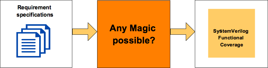
    Figure 1: Specification to functional coverage magic possible?

    I replied “No”. It cannot.

    But then after the presentation, questioned myself as to, why not?

    No, no still not brave enough to parse the standard specifications use natural language processing (NLP) to extract the requirements and generate the functional coverage from it. But we have taken first step in this direction. It’s a baby step. May be some of you might laugh at it.

    We are calling it as high level specification model based functional coverage generation. It has some remarkable advantages. As every time, I felt this is “the” way to write functional coverage from now on

    Idea is very simple. I am sure some of you might have already doing it as well. Capture the specification in form of data structures. Define bunch of APIs to filter, transform, query and traverse the data structures. Combine these executable specifications with our python APIs for SystmVerilog functional coverage generation. Voila, poor man’s specification to functional coverage generation is ready.

    Yes, you need to learn scripting language (python in this case) and re-implement some of the specification information in it. That’s because SystemVerilog by itself does not have necessary firepower to get it all done. Scared? Turned off? No problem. Nothing much is lost. Please stop reading from here and save your time.

    Adventurers and explorers surviving this hard blow please hop on. I am sure you will fall in love with at least one thing during this ride.

    How is this approach different?

    How is this approach different from manually writing coverage model? This is a very important question and was raised by Faisal Haque.

    There are multiple advantages, which we will discuss later in the article. In my view single biggest advantage is making the coverage intent executable by truly connecting the high-level model of specifications to functional coverage. No we are not talking about just putting specification section numbers in coverage plan we are talking about really capturing the specification and using it for generation of functional coverage.

    Let me set the expectations right, this approach will not figure out your intent. The idea is about capturing and preserving human thought process behind the functional coverage creation in executable form. So that it can be easily repeated when things change. That’s all. It’s a start and first step towards specifications to functional coverage generation.

    Typically functional coverage is implemented as set of discrete independent items. The intent and its connection to specifications are weak to non-existent in this type of implementation. Most of the intent gets either left behind in the word of excel plan where it was written or in the form of comments in the code, which cannot execute.

    Making intent executable

    Why capturing intent in executable form is important?

    We respect and value the human intelligence. Why? Is it only for this emotional reason? No. Making human intelligence executable is first step to artificial intelligence.

    Ability to translate the requirements specification into coverage plan is highly dependent on the experiences and depth of specification understanding of the engineer at the moment of writing it. If its not captured in the coverage plan it’s lost. Even the engineer who wrote the functional coverage plan may find it difficult to remember why exactly certain cross was defined after 6 months.

    Now this can become real challenge during the evolution and maintenance of the functional coverage plan as the requirements specifications evolve. Engineer doing incremental updates may not have luxury of the time as the earlier one had. Unless the intent is executable the quality of the functional coverage will degrade over period of time.

    Now if you are doing this design IP for only one chip and after that if you are throwing it away this functional coverage quality degradation may not be such a big concern.

    Let’s understand this little further with example. USB power delivery supports multiple specification revisions. Let’s say, we want to cover all transmitted packets for revision x.

    In manual approach we will discretely list protocol data units valid for revision x.

    For this listing you scan the specifications, identify them and list them. Only way to identify them in code as belonging to revision x is either through covergroup name or comment in the code.

    In the new approach you will be able to operate on all the protocol data units supported by revision x as a unit through APIs. This is much more meaningful to readers and makes your intent executable. As we called out, our idea is to make coverage intent executable to make it adaptable. Let’s contrast both approaches with another example.

    For example, let’s say you want to cover two items:

    • All packet transmitted by device supporting revision 2.0
    • Intermediate reset while all packet transmitted by device supporting revision 2.0

    If you were to write discrete coverage, you would have sampled packet type and listed all the valid packet types of revision 2.0 as bins. Since bins are not reusable in SystemVerilog you would do copy and paste them across these two covergorups.

    Now imagine, if you missed a packet type during initial specification scan or errata containing one more packet type came out later, you need to go back and add this new type at two different places.

    But with this new approach, as soon as you update the specification data structure with new type you are done. All the queries requesting revision x will automatically get updated information. Hence all the functional coverage targeted to revision x will be automatically updated.

    Remember initially it may be easy to spot two places where the change is required. But when you have hundreds of covergroups it will be difficult to reflect the incremental changes to all the discrete covergroups. It will be even more difficult when new engineer has to do the update without sufficient background on the initial implementation.

    In the USB Power delivery case study you will be able to see how to put this concept into action.

    Benefits

    What are the benefits of this approach?

    With high-level specification model based functional coverage the abstraction of thought process of writing coverage moves up and it frees up brain bandwidth to identify more items. This additional brain bandwidth can significantly help improve the quality of functional coverage plan and hence the overall quality of functional verification.

    Benefits of high-level model based functional coverage generation:

    • Intent gets captured in executable form. Makes it easy to maintain, update and review the functional coverage
    • Executable intent makes your coverage truly traceable to specification. Its much better than just including the specification section numbers which leads to more overhead than benefit
    • Its easy to map the coverage from single specification from different components points of view (Ex: USB device or host point of view or PCIe root complex or endpoint or USB Power delivery source or sink point of view) from single specification model
    • Easy to define and control the quality of coverage controlled by the level of details in the coverage required for each feature (Ex: Cover any category, cover all categories or cover all items in each category)
    • Easy to support and maintain multiple versions of the specifications
    • Dynamically switch the view of the coverage implemented based on the parameters to ease the analysis (Ex: Per speed, per revision or for specific mode)

    Architecture

    How to go about building high-level specification model based functional coverage?

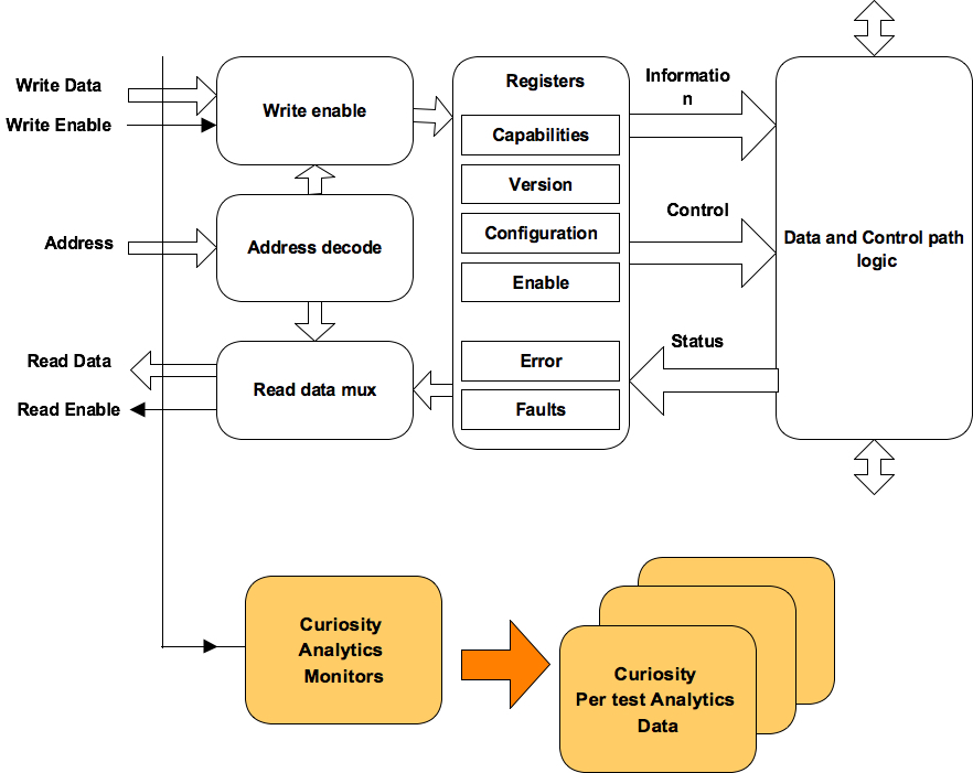
    First let’s understand the major components. Following is the block diagram of the high-level specification model based functional coverage. We will briefly describe role and functionality of each of these blocks. This diagram only shows basic building blocks.

    Later we will look at the case studies where we will see these blocks in action making their explanations more clear. It will also guide how to implement these blocks for your project as well.

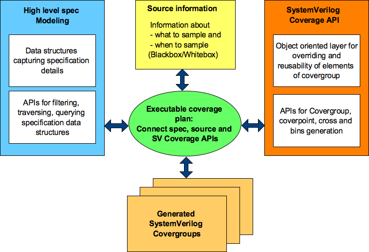
    Figure 2: Block diagram of high-level specification model based functional coverage generation

    Executable coverage plan

    Executable coverage plan is the block that actually hosts all the functional coverage items. It’s coverage plan and its implementation together.

    It does the implementation of functional coverage items by connecting the high-level specification model, source of information and SV coverage APIs. The APIs utilized, specification information accessed and relations of various items utilized preserves the intent in executable form.

    User still specifies the intent of what to cover.

    It won’t read your mind but you will be able to express your thoughts at higher level of abstractions and more closer or specifications and in highly programmable environment that is much more powerful that SystemVerilog alone.

    High-level specification modeling

    This block is combination of set of data structures and APIs.

    Data structures capture high-level information from the specifications. These data structures can be capturing information about properties of different operations, state transition tables representing the state machines, information about timers as to when they start, stop, timeout or graphs capturing various forms of sequences. Idea here is capture the relevant information about the specification that is required for the definition and implementation of the functional coverage. Choose the right form of data structures that fit the purpose. These data structures will vary from domain to domain.

    APIs on the other hand process the data structures to generate different views of the information. APIs can be doing filtering, combinations, permutations or just ease access to the information by hiding the complexity of data structures. There is some level of reuse possible for these APIs across various domains.

    Using these set of data structures and APIs now we are ready to translate the coverage plan to implementation.

    Information source

    Specification data structures may define the structure of operations but to cover it, we need to know how to identify the completion of operation, what is the type operation of operation completed and current values of its properties etc.

    Information source provides the abstraction to bind the specification information to either test bench or design RTL to extract the actual values of these specification structures. This abstraction provides the flexibility to easily switch the source of coverage information.

    Bottom line stores information about sources that are either sampled for information or provides triggers to help decide when to sample.

    SystemVerilog Coverage API in Python

    Why do we need these APIs, why can’t we just directly write it in SystemVerilog itself?

    That’s because SystemVerilog covergroup has some limitations, which prevent the ease of reuse.

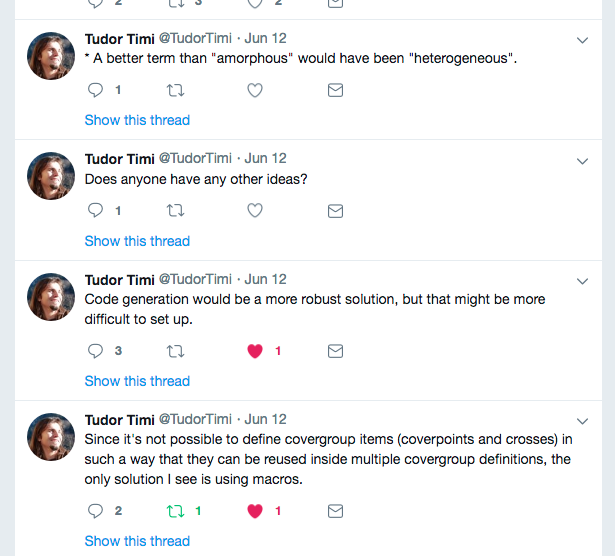
    Limitations of SystemVerilog Covergroup

    SystemVerilog functional covergroup construct has some limitations, which prevents its effective reuse. Some of the key limitations are following:

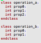
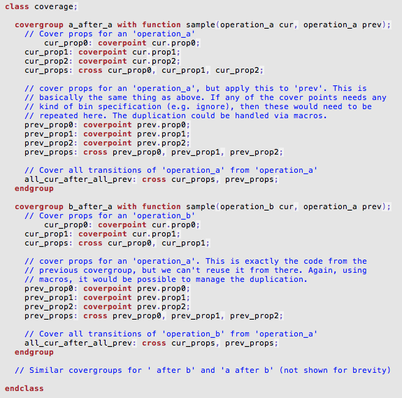
    • Covergroup construct is not completely object oriented. It does not support inheritance. What it means is you cannot write a covergroup in base class and add, update or modify its behavior through derived class. This type of feature is very important when you want to share common functional coverage models across multiple configurations of DUT verified in different test benches and to share the common functional coverage knowledge
    • Without right bins definitions the coverpoints don’t do much useful job. The bins part of the coverpoint construct cannot be reused across multiple coverpoints either within the same covergroup or in different covergroup
    • Key configurations are defined as crosses. In some cases you would like to see different scenarios taking place in all key configurations. But there is no clean way to reuse the crosses across covergroups
    • Transition bin of coverpoints to get hit are expected to complete defined sequence on successive sampling events. There is no [!:$] type of support where the transition at any point is considered as acceptable. This makes transition bin implementation difficult on relaxed sequences

    Coverage API Layering

    At VerifSudha, we have implemented a Python layer that makes the SystemVerilog covergroup construct object oriented and addresses all of the above limitations to make the coverage writing process more productive. Also the power of python language itself opens up lot more configurability and programmability.

    Based on this reusable coverage foundation we have also built many reusable high level coverage models bundled which make the coverage writing easier and faster. Great part is you can build library of high-level coverage models based on best-known verification practices of your organization.

    These APIs allows highly programmable and configurable SystemVerilog functional coverage code generation.

    Fundamental idea behind all these APIs is very simple.

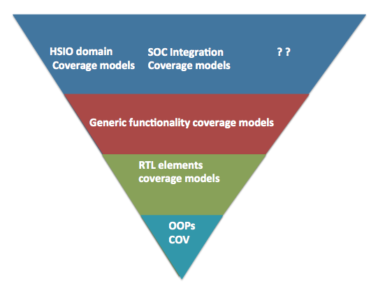
    Figure 3: SV Coverage API layering

    We have implemented these APIs as multiple layers in python.

    Bottom most layer is basic python wrappers through which you can generate the functional coverage along with the support for object orientation. This provides the foundation for building easy to reuse and customize high-level functional coverage models. This is sufficient for the current case study.

    RTL elements coverage models cover various standard RTL logic elements from simple expressions, CDC, interrupts to APPs for the standard RTL element such as FIFOs, arbiters, register interfaces, low power logic, clocks, sidebands.

    Generic functionality coverage models are structured around some of the standard high-level logic structures. For example did interrupt trigger when it was masked for all possible interrupts before aggregation. Some times this type of coverage may not be clear from the code coverage. Some of these are also based on the typical bugs found in different standard logic structures.

    At highest-level are domain specific overage model. For example many high-speed serial IOs have some common problems being solved especially at physical and link layers. These coverage models attempt to model those common features.

    All these coverage models are easy to extend and customize as they are built on object oriented paradigm. That’s the only reason they are useful. If they were not easy to extend and customize they would have been almost useless.

    Implementation

    • Backbone of these APIs is data structure for the SystemVerilog covergroups modeled as list of dictionaries. Each of the covergroup being a dictionary made up of list of coverpoint dictionaries and list of cross dictionaries. Each of the coverpoint and cross dictionaries contain list of bin dictionaries
    • These data structures are combined with simple template design pattern to generate the final coverage code
    • Using layer of APIs on these data structure additional features and limitations of SystemVerilog covergroup are addressed
    • Set of APIs provided to generate the reusable bin types. For example if you want to divide an address range between N equal parts, you can do it through these APIs by just providing the start address, end address and number of ranges
    • There are also bunch of object types representing generic coverage models. By defining the required properties for these object types covergroups can be generated
    • Using python context managers the covegroup modeling is eased off for the user

    Any user defined SystemVerilog code can co-exist with these APIs. This enables easy mix of generated and manually written code where APIs fall short.

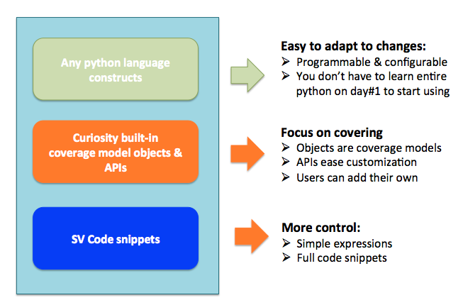
    Figure 4: What to expect from APIs

    Structure of user interface

    All the APIs essentially work on the object. Global attributes can be thought of as applicable to entire covergroup. For example if you specified bins at the global level it would apply to all the coverpoints of the covergroup. Not only the information required for coverage generation but also description and tracking information can be stored in the corresponding object.

    This additional information can be back annotated to simulator generated coverage results helping you correlate your high-level python descriptions to final coverage results from regressions easily.

    Also the APIs support mindmaps and Excel file generations to make it easy to visualize the coverage plan for reviews.

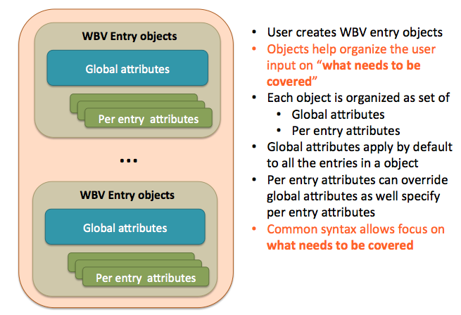
    Figure 5: Structure of user interface for objects

    Source information

    Covergroups require what to sample and when to sample.

    This is the block where you capture the sources of information for what to sample and when to sample. It’s based on very simple concept like Verilog macros. All the coverage implementation will use these macros, so that it abstracts the coverage from statically binding to source of the information.

    Later these macros can be initialized with the appropriate source information.

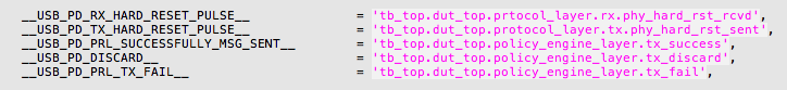
    Snippet 1: Specifying source information

    This flexibility allows using information source from either between the RTL and test bench. Easily be able to switch between them based on need.

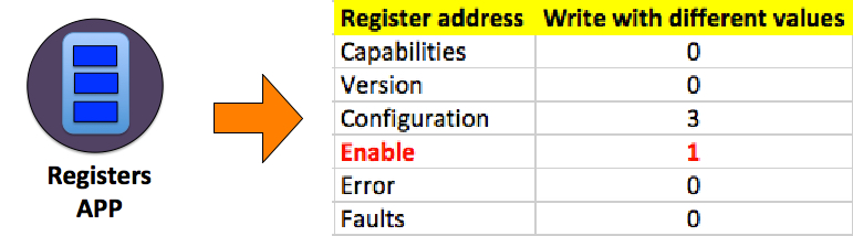
    Following code snippets showcase how covergroup implementation for simple read/write and address can be done using either RTL design or test bench transactions.

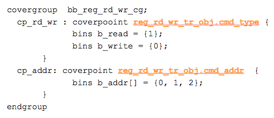
    Snippet 2: Coverage generated using testbench transaction

    Coverpoints in snippet 2 are sampling the register read write transaction object (reg_rd_wr_tr_obj). Sampling is called on every new transaction

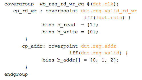
    Snippet 3: Coverage generated using DUT signals

    Coverpoints in snippet 3 are sampling the RTL signals to extract the read/write operation and address. Sampling is called on every new clock qualified by appropriate signals.

    Summary:

    Functional coverage is one of the last lines of defense for verification quality. Being able to repeatedly do a good job and do it productively will have significant impact on your quality of verification.

    Initially it may seem like lot of work, you need to learn a scripting language and learn different techniques of modeling. But pay off will not only for the current project but throughout the lifetime of your project by easing the maintenance and allowing you to deliver the higher quality consistently.

    Download a case study of how this is applied to USB Power delivery protocol layer coverage.

  • PIPE 5.0: 34% signal count reduction for PCI Express 5.0

    PIPE specification version 5.0 has been released on September 2017. Number “5.0” has special significance this time. From PIPE 5.0 onwards, supports or protocols is extended to 5 different interface protocols and it’s gearing up for PCIe 5.0.

    Top 3 highlights of changes in PIPE spec version 5.0 are:

    1. 34%  signal count reduction on PIPE interface
    2. SerDes support. PIPE width increasing up to 64-bits for PCie SerDes only
    3. Support for two new protocols: ConvergedIO and DisplayPort along with PCIe, USB and SATA

    In the following blog, we would like to discuss more about the point#1, which is the significant benefit. Layout engineers will surely celebrate this change with many fat signals being moved to message registers.

    There is 34 % reduction in PIPE signal count. In PIPE 5.0, all legacy PIPE signals without critical timing requirements are mapped to message bus registers.

    Breakup of reduction across various signal categories is as following:

    Table summarizing the signal count reduction by each category

    Signal count is number of logical signals defined in PIPE specifications.

    Ex: Group of wires such as PowerDown[1:0] is considered a single signal in above counts.

    From PIPE specification 4.4.1 onwards a new message interface was introduced. Any new features added from version 4.4.1 onwards will be made available only via message bus accesses unless they have critical timing requirements that need dedicated signals.

    This pin count reduction implementation will be mandatory for PCIe 5.0 implementations. PCIe 4.0 can continue to use legacy pin interface. USB 3.2 and SATA can optionally utilize it.

    Magic that makes this signal count reduction possible is message bus. So, let’s briefly look at message bus.

    What is message bus?

    The message bus interface provides a way to initiate and participate in non-latency sensitive PIPE operations using small number of wires and it enables future PIPE operations to be added without adding additional wires. The use of this interface requires the device to be in a power state with PCLK running.

    Control and status bits used for PIPE operations are mapped into 8-bit registers that are hosted in 12-bit address spaces in the PHY and MAC.

    The registers are accessed via read and write commands driven over two 8-bit signals M2P_MessageBus[7:0] and P2M_MessageBus[7:0]. Both of these signals are synchronous to PCLK and are reset with Reset#.

    All the following are time multiplexed over the bus from MAC and PHY:

    • Commands (write_uncommitted, write_committed, read, read_completion, write_ack)
    • 12-bit address used for all types and read and writes
    • 8-bit data either read or written

    A simple timing demonstrates its usage:

    Message bus time sharing

    PIPE 4.4.1 utilized the message bus for the Rx margining sequence. This helped standardize the process to measure performance of link in live system. Performance of link varies due to crosstalk, jitter and reflections all which are time varying as they are subjected to PVT (Process/Voltage/Temperature) variations.

    More information about message bus can be looked up in the Section 6.1.4 of the PIPE 5.0 specification.

    Message address space

    Message address space utilization has increased significantly in the PIPE 5.0. Also it’s structured to make address space organization cleaner.

    MAC and PHY each implement unique 12-bit address spaces. These address spaces will host registers associated with the PIPE operations. MAC accesses PHY registers using M2P_MessageBus[7:0] and PHY accesses the MAC registers using the M2P_MessageBus[7:0].

    The MAC and PHY access specific bits in the registers to:

    • Initiate operations
    • Initiate handshakes
    • Indicate status

    Each 12-bit address space is divided into four main regions each of size 1024KB:

    • Receiver address region: Receive operation related
    • Transmitted address region: Transmitter operation related
    • Common address region: Common to both transmitter and receiver
    • Vendor specific address region: For registers outside the scope of specifications

    These regions support configurable Tx/Rx pairs. Up to two differential pairs are assumed to be operational at any one time. Supported combinations are:

    • One Rx and One Tx pair
    • Two tx pair
    • Two rx pair

    Legacy PIPE signals mapped to message registers

    There are 21 legacy PIPE signals mapped to message bus registers. Following is mindmap representation of signal listing and regions to which they are mapped.

    More information about exact message bus register mapping can be looked up in the Section 7.0 of the PIPE 5.0 specification.

    Grouping of PIPE signals mapped to Message address space

    We hope this helps you get quick glance of what is happening and how it can help you reduce the signal count on the PIPE interface.

    This brings in changes to both the MAC and PHY logic. Just the toggle coverage of the PIPE interface is not sufficient to ensure successful integration.

    We offer  PIPE interface functional coverage model that is comprehensive, configurable and easy to integrate. It can help you reduce the risk of the changes and get the confidence you need in your integration.

    [easy_media_download url=”https://www.verifsudha.com/download/1924/” color=”orange_dark” text=”Download brochure” width=”200″]


  • How to close last 20% verification faster?

    How you execute your first 80% of verification project, decides how long it will take to close the last 20 %.

    Last 20%, is hardest because during first 80%, project priorities typically change multiple times, redundant tests get added, disproportionate seeds are allocated to constrain random tests and often distributions on constraints are ignored or effects are not qualified. All this leads to bloated regressions, which are either underworking on right areas or overworking on wrong areas.

    Visualization of underworking or overworking regression
    Visualization of underworking or overworking regression

    It’s either of the underworking or overworking regression cases that make the closure the last 20% harder and longer. This symptom cannot be identified by the code coverage and requirements driven stimulus functional coverage alone.

    Let’s understand what are underworking regressions, overworking regressions and what are their effects.

    Overworking regressions

    Overworking regressions are overworking because they are failing to focus on right priorities. This happens due to following reasons.

    Good test bench architecture is capable of freely exploring the entire scope of the requirement specifications. While this is perfectly right way to architect the test bench but it’s equally important to tune it to focus on right areas depending on priorities during execution. Many designs are not even be implementing the complete specifications and the applications using design may not even be completely using all the features implemented.

    Test bench tuning is implemented by test cases. Test case tunes the constraints of stimulus generators and test bench components to make test bench focus on right areas.

    Due to complex interaction of test bench components and spread out nature of randomization it’s not possible to precisely predict of the effects of tuning the constraints in test bench. Especially when you have complex designs with lots of configurations and large state space.

    In such cases without proper insights, the constrained random could be working in area that you don’t care much. Even when it finds the bugs in this area they end up as distractions rather than value add.

    Right area of focus is dependent on different criteria’s and can keep changing. Hence it needs continuous improvisations. It’s not fixed target.

    Some of key criteria’s to be considered are following:

    • New designs
      • Application’s usage scope of design’s feature
      • Important features
      • Complex features
      • Key configurations
      • Area’s of ambiguity and late changes
    • Legacy designs
      • Area of design impacted due to features update
      • Areas of design which were not important in last version but are now in current version
      • Areas where most of the bugs were found in last revision
      • Design areas changing hands and being touched by new designers

    Underworking regressions

    In contrast to overworking regressions, underworking regressions slack. They have accumulated the baggage of the tests that effectively are not contributing to the verification progress.

    Symptoms of underworking regressions are

    • Multiple tests exercising same feature in exactly same way
    • Tests exercising features and configurations without primary operations
    • Tests wasting the simulation time with large delays
    • Test with very little randomization getting larger number of seeds

    Legacy designs verification environments are highly prone to becoming underworking regressions. This happens as tests accumulate over period of time without clarity on what was done in the past. Verification responsibility shifts hands. Every time it does both design and verification dilutes till new team gets hold of it.

    This intermediate state of paranoia and ambiguity often gives rise to lots of overlapping and trivial tests being added to regression. This leads to bloated and underperforming regressions hogging the resources.

    Effects of underworking or overworking regressions

    Both overworking and underworking regressions reflect in the absurd number of total tests for given design complexity and long regression turn around times.

    This results in wastage of time; compute farm resources, expensive simulator licenses and engineering resources. All this additional expenses without desired level of functional verification quality.

    Both overworking and underworking regressions are spending their time on non-critical areas. So the resulting failures from them lead to distraction of engineers from critical areas. When number of failures debugged to number of right priority RTL bugs filed ratio starts to go down, it’s time to poke at regressions.

    Please note simulator performance is not keeping up with the level of complexity.  If you are thinking of emulation keep following in mind:

    Does emulation really shorten the time?
    Does emulation really shorten the time?

    Hence simulation cycles have to be utilized responsibly. We need to make every simulation tick count.

    Which means we need to optimize regressions to invest every tick, in proportion to priority and complexity of the features,  to achieve right functional verification quality within budget.

    We offer test suite stimulus audits using our framework  to provide insights, that can help you align your stimulus to your current project priorities, ensuring stimulus does what matters to your design and reducing the regression turn around time.

    Net effect you can optimize your regression to close your last 20% faster.

  • When to write to functional coverage plan?

    The question is at what phase of the verification project should one be writing the functional coverage plan?

    Please note that, this question never comes up for the test plan (primarily stimulus plan) and checks or assertion plan. Most of the teams agree that they need to be written at the beginning of the verification project. There is not much of debate there.

    So, why does this question arise only for coverage plan?

    Functional coverage is a metric. Metric implementation by itself does not contribute directly towards completion of task being performed.

    Writing functional coverage will not directly contribute to completion of functional verification. Its correct definition, implementation, analysis and action based on coverage results will contribute to quality of verification completed. Since its multiple hops away from end result and effects are only visible in long term, there is always hesitation to invest in it.

    Anyway let’s go back to our original question and answer it.

    Since our worldview is binary, let’s select two popular answers:

    1. At the beginning of the verification project along with the test plan and checks plan
    2. Somewhere towards later stage of verification project, let’s say when the verification is about 70 – 80 % complete

    Let’s debate on pros and cons of both the answers.

    Here are some arguments on answer #1:

    At the start of project everything is uncovered. So what’s point of having the functional coverage plan? We know our stimulus generation is not up yet so everything is uncovered so why write the functional coverage plan?

    That’s true. From realities of project execution we all know, heat of the project has not picked up yet. So why not use this time to complete the functional coverage plan?

    That seems like reasonable argument.

    Well but we do not have complete knowledge of requirements specifications and nor do we know much about our stimulus as to what we are going to randomize. So what do we capture in the functional coverage plan?

    Okay, let’s say for argument sake even if we write functional coverage plan based on verification requirements. Do we need to start implementation of it as well along with stimulus and checkers? If answer is No, then why write it?

    We all know priorities of features change significantly during the course the execution of project. If we invest in elaborate functional coverage implementation for low priority features the high priority features will suffer. Not all features are made equal. So resource distribution has to be in proportion to priority and importance of the feature. How do we deal with this scenario?

    Let’s pause arguments on this answer and let’s also look at the answer #2. At the end we can try to find the right trade off that helps find satisfactory answers for most of the arguments.

    Here are some arguments on answer #2:

    At about 70% completion of verification, the heat of project execution is reaching close to its peak. The best of your engineering resources are tied to goals focused on closure around stimulus generation and checkers.

    At this point, isn’t it tempting to say code coverage is sufficient? Why invest time in planning and implementing the functional coverage? In the same time we could be writing more tests to close on those last few holes of code coverage.

    Even if we do write the functional coverage plan, are we not already biased towards the stimulus we have already created? Although stimulus coverage is valuable but stimulus coverage alone, can it really help us achieve the desired verification quality for a given design?

    We are already short on time and resources. We don’t have time to write functional coverage plan at this point. Even if we do write a good functional coverage plan magically do we have time to implement the complete functional coverage plan?

    Dizziness

    Enough. That’s enough. Stop these arguments. I knew it. There isn’t any correct answer, so whatever we were doing was correct. You just made me dizzy with all these arguments.

    After hearing all arguments
    After hearing all arguments

    No, wait. Don’t loose the patience.

    Here are some suggestions:

    • Functional coverage plan has to be created along with the test plan and checks plan at the start of the project
    • Functional coverage plan has to be focused from what functional verification needs to deliver to meet the requirements and micro-architecture specifications
    • Functional coverage need not be tightly coupled to stimulus generation. What if your stimulus generation is incorrect or incompletely defined? Its good idea to be focused on overall verification requirements point of view rather than how we generate stimulus to meet those verification requirements. Does it make sense?
    • No need to rush to implement the complete functional coverage plan as soon as its written
    • Tie the functional coverage items to different milestones of the project which even stimulus and checkers have to meet
    • Only implement those relevant for the upcoming milestones. This approach if followed well can help accelerate the code coverage closure at the end. Note that code coverage is not useful in early stages of the project
    • One can keep stimulus and checkers two steps ahead of functional coverage plan implementation in terms of milestones but its important to keep building functional coverage parallel to validate the verification progress to get the best out of it
    • Functional coverage plan’s trackability, implementation and results analysis has to be coupled together along with high flexible and adaptability to keep up with the changing project priorities

    Bottom line we need to understand that the functional coverage is not short-term result oriented activity. We also need to note that its additional work that does not immediately contribute to verification completion. So any inefficiency in the process of writing plan, implementation and its analysis means quality of metric itself will be compromised. That will defeat the whole purpose of having metric in first place. Metric implementation is additional work and additional work has to be always easier in order for it to be done effectively.

    There is not much of benefit of spreading functional coverage thin over many features. If it’s not possible to do justice to all features then develop functional coverage for prioritized sub-set of features.

    Functional coverage: A+ or nothing

    Inspired by the discussion that took place during a  presentation at one of customer premise. Contributions are made by many. Thanks everyone.

    Author: Anand Shirahatti

  • Functional coverage planning: Why we miss critical items?

    World of dynamic simulation based functional verification is not real. Verification architects abstract reality to create the virtual worlds for design under test (DUT) in simulation. Sometimes it reminds me of the architectures created in the movie inception. It’s easy to lose track of what is real and what is not. This leads to critical items being missed in the functional coverage plan. In this article we will look at three point of views to look at feature while doing functional coverage planning to increase chances of discovering those critical scenarios.

    Huh..! In the world of functional verification how do I know, what is real and what is not?

    In simple words if your design under test (DUT) is sensitive to it then its real and if it’s not sensitive to it then it’s not real. Requirements specification generally talks about the complete application. Your DUT may be playing one or few of the roles in it. So it’s important to understand what aspects the application world really matter to your design.

    The virtual nature of the verification makes it difficult to convey the ideas. In such cases some real life analogies come in handy. These should not be stretched too far but should be used to make a focused point clear.

    In this article, we want to talk about how to look at the requirements specifications and micro-architecture details while writing coverage plan. We want to emphasize the point micro-architecture details are equally important for functional coverage plan. Often verification teams ignore these. It affects the verification quality. Let’s look at the analogy to specifically understand why micro-architecture details matter to verification engineer? How much should he know? Let’s understand this with analogy.

    Analogy

    Let’s say patient approaches orthopedic surgeon to get treatment for severe back pain. Orthopedic surgeon prescribes some strong painkillers, is it end of his duty? Most painkiller tablets take toll on stomach and liver health. Some can even trigger gastric ulcers. What should orthopedic surgeon do? Should he just remain silent? Should he refer him to gastroenterologist? Should he include additional medications to take care of these side effects? In order to include additional medications to take care of side effects how far should orthopedic surgeon get into field of gastroenterology? Reflect on these based on real life experiences. If you are still young then go talk to some seniors.

    The same dilemma and questions arise when doing functional coverage planning. Functional coverage planning cannot ignore the micro-architecture. Why?

    When the requirements specifications are translated to micro-architecture, it introduces its own side effects. Some of these can be undesirable. If we choose to ignore it, we risk those undesirable side effects showing up as bugs.

    Dilemma

    Well we can push it to designers saying that they are the ones responsible for it. While it’s true to some extent but only when designer’s care for verification and verification cares for design first pass silicon dreams can come true. We are not saying verification engineers should be familiar with all intricacies of the design but the basic control and data flow understanding cannot be escaped.

    Functional coverage planning: 3 points of view

    All the major features have to be thought out from three points of views while defining functional coverage. There can be certain level of redundancy across these but this redundancy is essential for the quality.

    Those three points of view are:

    1. Requirements specification point of view
    2. Micro-architecture point of view
    3. Intersection between requirements and micro-architecture point of view

    For each of these how deep to go is dependent on the sensitivity of the design to the stimulus being thought out.

    Let’s take an example to make this clearer.

    Application of 3 points of view

    Communication protocols often rely on timers to figure out the lost messages or unresponsive peers.

    Let’s build simple communication protocol. Let’ say it has 3 different types of request messages (M1, M2, M3) and single acknowledgement (ACK) signaling successful reception. To keep it simple unless acknowledged the next request is not sent out. A timer (ack_timer) is defined to takes care of lost acknowledgements. Range of timer duration is programmable from 1ms to 3ms.

    In micro-architecture this is implemented with simple counter that is started when any of requests (M1, M2, M3) is sent to peer and stopped when the acknowledgement (ACK) is received from peer. If the acknowledgement is not received within the pre-defined delay a timeout is signaled for action.

    So now how do we cover this feature? Let’s think through from all three points of view and see what benefits do each of these bring out.

    Requirements specification point of view:

    This is the simplest and most straightforward among the three. Coverage items would be:

    • Cover successful ACK reception for all three message types
    • Cover the timeout for all three message types
    • Cover the timeout value for Min(1 ms), Max(3 ms) and middle value( 2ms)

    Don’t scroll down or look down.

    Can you think of any more cases? Make a mental note; if they are not listed in below sections, post them as comments for discussion. Please do.

    Micro-architecture point of view:

    Timer start condition does not care about which message type started it. All the message types are same from the timer point of view. From timer logic implementation point of view, timeout due to any one message type is sufficient.

    Does it mean we don’t need to cover timeout due to different message types?

    It’s still relevant to cover these from requirements specification point of view. Remember through verification we are proving that timeout functionality will work as defined by specification. Which means, we need to prove that it will work for all three-message types.

    Micro-architecture however has its own challenges.

    • Timeout needs to covered multiple times to ensure the mechanism of timer reloading takes place correctly again after timeout
    • System reset in the middle of timer running followed by timeout during operation needs to be covered. It ensures that system reset in middle of operation does reset the timer logic cleanly without any side effects (difference between power on reset vs. reset in middle)
    • If the timer can be run on different clock sources it needs to be covered to ensure it can generate right delays and function correctly with different clock sources

    Requirement specification may not care about these but these are important from micro-architecture or implementation point of view.

    Now let’s look at intersection.

    Intersection between requirements and micro-architecture point of view

    This is the most interesting area. Bugs love this area. They love it because of intersection, shadow of one falls on another creating dark spot. Dark spots are ideal places for the bugs. Don’t believe me? Let’s illuminate and see if we find one.

    Generally synchronous designs have weakness around +/- 1 clock cycle around key events. Designers often have to juggle lot of conditions so they often use some delayed variants of some key signals to meet some goals.

    Micro-architecture timeout event intersecting with external message reception event is interesting area. But requirements specification cares for acknowledgement arriving within timeout duration or after timeout duration.

    What happens when acknowledgement arrives in following timing alignments?

    • Acknowledgement arrives just 1 clock before timeout
    • Acknowledgement arrives at the same clock as timeout
    • Acknowledgement arrives just 1 clock after timeout

    This is area of intersection between the micro-architecture and requirement specification leads to interesting scenarios. Some might call these as corner cases but if we can figure out through systematic thought process, shouldn’t it be done to the best possible extent?

    Should these cases of timing alignment be covered for all message types? Its not required because we know that timer logic is not sensitive to message types.

    Another interesting question is why not merge the point views #1 and #2? Answer is thought process has to be focused on one aspect at a time, enumerate it fully and then go to other aspect enumerate it fully then go figure out the intersection between them. Any shortcuts taken here can lead to scenarios being missed.

    Closure

    This type of intent focused step-by-step process enhances the quality of functional coverage plans and eases the maintenance when features are updated.

    Some of you might be thinking, it will take long time and we have schedule pressure and lack of resources. Let’s not forget quality is remembered long after the price is forgotten.

  • Classic automation in Functional verification

    There are various areas of the functional verification, which requires automation beyond scope of standard simulator bundled tool chains. For some of these areas there is lack of standard third party tools or there is resistance to adopt external tools due to legacy reasons. Whatever are the reasons, verification engineers often roll up their sleeves up and create an in-house solution for these problems.

    Verification engineers mostly rely on perl, python, TCL and shell scripting for most of the automations. Some do venture to the C, C++ and Java but they are rare. Let’s not forget they have full time verification job to take care as well.

    Let’s look at few popular problems that often see in-house automations. All these in-house automations can be broadly classified into three categories.

    Data mining and aggregation

    Regression management

    Most companies have some proprietary solution for this.

    This problem involves launching the regressions on compute farms, periodic monitoring to find out the status of run and finally publishing the status of run at the end of regression.

    Verification plan management:

    All big 3 EDA vendors bundle some form of solutions with their simulator. They are quite popular as well. But sometimes for tighter integration with the in-house regression management system verification engineers do build custom solutions in this space.

    These typically manifest in the form of verification plans, being either maintained as text or in the form of data structures to serve as input to the regression management systems.

    These help in maintaining the tests, their variations, descriptions and tracking information. Using this total tests, their variations, seeds allocation the tests to be written can all be figured out.

    Bugs statistics

    Bugs management can be third party or in-house tool. As this is a critical tool for quality management, often companies invest in building their own custom tool to suit to their product lines and flows. Of-course this out of reach of verification engineers and falls in typical software engineering category.

    These bug management systems provide the browser-based interface to access the bug information and statistics. Along with that they do expose web service interfaces such as SOAP.

    To find out various bug statistics frequently utilities are created using the SOAP interface. Eventually these also get integrated with the verification plan and regression management system to get clear idea of current status. Integration for example helps in finding regression failures that have bugs open versus ones where debugging is in progress.

    All these type of automation brings in clarity and transparency.

    Utilities for these require good understanding of linux commands, Make, file io and regular expressions.

    Code generation

    Lot of the code that is written in the high-level verification languages and verification methodologies is boilerplate code. It has lot repetition. Along with that there are some code that needs to be parameterized but cannot be written with only language provided constructs.

    Register abstraction layer (RAL)

    RTL register block generation is common practice and many companies had custom flow for it well before verification methodologies came up with RAL.

    Naturally the same information about registers was leveraged for the RAL code generation for the verification. Of-course verification purists may not like the fact that designs code and verification code is generated from same source information.

    UVM RAL code, functional coverage for registers and some basic register read/write tests can be automatically generated.

    Basic UVM environment

    This can be typically done in two ways.

    First simple approach is to generate the code to get started with the initial environment development. Here all the placeholder classes for complete UVM environment are generated. Once generated, users update their actual code inside the generated code. Automation is limited to only one time generation at the beginning.

    Second approach is less complete but more practical. Here partial or base environment is generated. Base environment includes regular stuff like SystemVerilog interface generation, hooking them to right agents, instancing agents and connecting TLM ports between them etc. There on these base environments are extended and additional functionality that is not easy to automate is added.

    Assertions and functional coverage generation

    Assertions and functional coverage for regular RTL with highly parameterised designs are also automatically generated to keep up with the design changes. Some examples of such designs include anything that is multiple ports, switches, hubs or network on chip (NOC) etc.

    Knowingly or unknowingly the concepts of the design patterns are used in code generation.

    High level specification model based functional coverage generation is another approach that can help you capture the intent in executable form.  It’s a first baby step towards specification to functional coverage generation.

    Linting

    Yes, checklist is one of the important mechanisms to ensure everything is completed. Checklists are tied to important milestones. Some of the checklist items needs to be repeated on multiple milestones. Some of these checklist items can be very specific to organizations and hence require automation in the form linting to repeat them.

    Linting term used here in broad sense. It can be code linting or linting anything. Basically doing some checks.

    Some examples are:

    • Enforcing some organization specific coding guidelines or identifying potential gotchas in verification code (fork usage for instance)
    • Identifying usage of invalid, unsupported or deprecated command line arguments in test command lines
    • Identifying TODO in the code. TODO can be represented in different ways. Capture all of them and check if they are present
    • No compile time or run time warnings

    Utilities for these are file io and regular expression driven.

    Beyond these lot of temporary tasks requiring analysis of large quantity of data like CDC reports, reset connectivity or coverage reports also see some partial automations to ease the task and reduce the possibility of something being missed.

    Getting some grip on basic scripting, regular expression and data structures can help you improve productivity of yourself and your team.

    This might be good starting point to improve your programming skills: 600 free online courses on programming