Category: Functional verification – Development

  • Functional coverage types – Black box vs. White box

    Functional coverage is one of the key metrics for measuring functional verification progress and closure. It complements by addressing the limitations of the code coverage. Functional coverage is one of the key factors contributing to quality of the functional verification.

    Code coverage holes are typically closed first followed by the functional coverage. So remember functional coverage is one of those last gates to catch the uncovered areas. After the design is signed off from functional coverage point of view, it’s one step closer to tapeout from functional verification point of view.

    Once the functional coverage is signed off, bugs hiding in the uncovered areas will most likely get discovered in silicon validation. The cost of bug increases significantly when its caught later in the ASIC verificaiton cycle. This emphasizes the importance of functional coverage. Please note functional coverage is not directly catching the bugs. It helps illuminate the various design areas to increase the probability of bugs being found. To make best use of it we need to understand different types of functional coverage.

    Functional coverage is implementation of the coverage plan created in planning phase. Coverage plan is part of, verification plan. It refers primarily to two sources of information for its verification requirements. Requirements specification and micro-architectural specification of the implementation. Functional coverage should address both of them.

    There are two types of functional coverage, black box and white box created to address both the requirements.

    Let’s look at them in more details.

    Yin-Yang of functional coverage
    Functional coverage types

    Black box functional coverage

    Functional coverage addressing the requirements specifications is referred to as black box functional coverage. It is agnostic to the specific implementation of requirements. It will not be dependent on micro-architectural implementation.

    Typically it’s extracted with the help of various test bench components. It also represents the coverage in the form of design’s, final application usage.

    Lets understand this better with simple example. Application usage, in processor world would mean instructions. One of the area for functional coverage would be to cover all the instructions and in all their possible programming modes like registers, direct memory, indirect memory etc. Another example from peripheral interconnect world, one of the coverage item can be to cover all the types of packets exchanged with various legal and illegal values for all the fields of packets.

    One of the best way to write black box functional coverage is to generate it from the specifications. This allows the intent of the coverage items to be preserved allowing the functional coverage to automatically evolve with the specification. Find out how you can take first step in specification to functional coverage.

    White box functional coverage

    Functional coverage covering the micro-architectural implementation is referred to as white box functional coverage.

    White box verification and its functional coverage is one of the under focused area. This is due to reliance on standard code coverage to take care of it. Verification engineers typically leave this space to be addressed by the design engineers. Design engineers do try to take care of this by adding assertions on assumptions and test point to see if the scenario of interest to implementation are covered.

    But for design engineers this is additional work among many others tasks. Thus it ends up not getting the focus desired.  This can sometime lead to very basic issues getting discovered in this area very late in game.

    White box functional coverage will be dependent on the specific design implementation. Typically, it will tap into internal design signals to extract the functional coverage. This tapping can be at design’s interface level or deep inside the design.

    Lets understand this with simple example. One of the white box coverage item in processor world can be instruction pipelines. Covering all possible instruction combinations taking place in instruction pipelines. Note that,  this will not be addressed by code coverage.

    In peripheral interconnect world it can be the FIFO’s in data path. Covering  different levels utilizations, including the full conditions. Transitions from empty to full to empty. Covering errors injected at certain internal RTL state. Covering number of clocks an interface experienced the stall. Covering all possible request combinations active at the critical arbiter interface. These are to name few cases. A simple LUT access coverage could have helped prevent famous pentium FDIV bug.

    White box coverage writing effort depends on complexity and size of the design. White box coverage writing effort can be reduced up to 3x easily by generating them instead of writing. Generation can happen as part of plug-ins in RTL or  using framework like curiosity.

    White box functional coverage and black box functional coverage can have some overlapping areas. There will bit of white box functional coverage in black box functional coverage and vice versa. Right balance of both black box and white box functional coverage provides the desired risk reduction and helps achieve the high functional verification quality.


  • Testbench logging

    Testbench logging is one of the under focused areas. It does not receive the level of attention it deserves. What testbench architects fail to realize is poor logging has direct impact on the debug efficiency. Logging also should be designed with same intensity as testbench architecture. Most of what is discussed below is all obvious things but still not widely adopted. One of the most pathetic and most easy to fix problem of the functional verification is logging.

    Logging refers to all the messages displayed by the testbench during test execution. Logging includes the error messages and debug messages. Error messages are printed when the check or assertion fails. The debug messages are printed by the different verification components of the testbench during their operation.
    (more…)

  • Testbench debug logging content and formatting

    Testbench logging is front end of debug. Debug log content refers to information used for understanding scenario created by test and insights into testbench operation for the purpose of debugging failures.

    Good log formatting is not just eye pleasing. Beauty is necessary but its definition is not always eye pleasing. Bottom line is logging should adapt seamlessly to it’s use case model. Beauty of logging is in the eyes of it’s use cases.


    (more…)

  • Testbench logging objectives and verbosity

    Testbench logging is front end of debug. Primary objective for logging is to provide clues into failure and help root cause the issue for failure. Logging objectives should be aligned to three phases of debug. This should be achieved with the help of verbosity.

    Logging messages are of two types.

    (more…)

  • Design under test (DUT) for Verification Engineer

    Understanding design under test (DUT) is very important for verification engineers. Remember RTL design gets taped out as final ASIC product. Sales of this product brings in the cash that pays for our salaries.

    Verification is activity that trains DUT to make it fit for use.

    Now key question from verification engineer’s point of view is, what aspects of DUT should be understood for purpose of verification?

    Verification requires understanding of the following aspects of the design:

    View of DUT for Verification engineer

    Micro-architecture – Data and Control

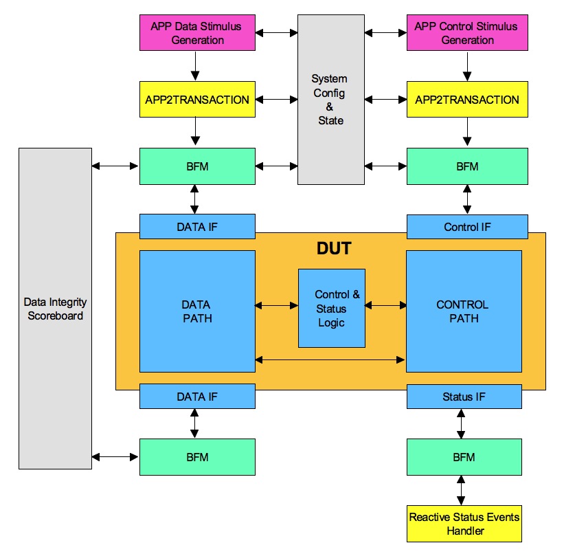
    DUT micro-architecture is division of the functionality for implementation. One of the key component of micro-architecture is to divide it into data and control functionalities. A very simple view of design is to look at it as transfer function. Data path implements the data transformation functions. Control path controls the data path for achieving the configured data transformations.
    (more…)

  • Effective randomization in Constrained Random Verification

    One of the key component of coverage driven constraint random verification environment is randomization. High-level verification languages provide various constructs to implement the randomization. However that is not the focus of this article.

    In spite of rich randomization constructs, many of the constrained random verification environments fail to achieve the optimum results either due to excessive or insufficient randomization. This article will focus on addressing how to hit that balance.

    How to effectively use the randomization to meet the verification goals? Let’s find out the answers by asking more questions and answering them below. We can call these as requirements for the randomization. Next in the series we will consider how to meet these requirements one of the popular HVLs.

    Why do we use randomization?

    Consider a design state space and feature combinations that are so large, that it’s practically impossible to enumerate and cover all of them exhaustively. This is a scenario, suitable to be addressed by randomization. Randomization of the stimulus will explore the state space and combinations, which we cannot manually enumerate.
    (more…)

  • Scripting

    Verification engineer without good scripting skills is a magician without magic wand.

    Scripting is primarily targeted to solving problems that are not directly related to the functional verification but related to the verification productivity enhancement. That does not mean it should not be used for the functional verification problems as well. It can be but most of functional verification problems are solved using specialized HVLs. HVLs are better suited for that. Typically in the areas where HVLs lack some capability is augmented with the conventional programming languages such as C/C++ rather than scripting languages. It’s changing recently. There are new developments taking place where simulators are providing the native integration to scripting languages. It will be interesting to see how this evolves.

    Scripting can be shell scripting or popular-scripting languages such as Perl, Python or TCL. The idea here is to reach the working prototype very quickly. Many times the scripting solution validity is time limited to certain phase of the project. It’s important to minimize the investments in such scripts and still quickly have a working solution.

    Productivity items can be in any of the four areas of the functional verification planning, development, regression and management.

    In planning, verification plan management is one of the candidates. One of the key requirements is to store the test plan, coverage plan and checks plan in easy to customize form and to match the results from simulation runs.

    In development, code generation can be one big area. Using the design patterns to enhance the code generation is growing fast. Initial development setup generation is a growing application.

    In regression management running regressions, grouping the related failures so that only one of them can be pursued for debugging, regression status generation, and regression failure tracking and linking it with the bugs that have been filed are few problems requiring scripting. This is one of the areas where lot of repetitive activities takes place and hence the need for the automation is quite high.

    In the verification project management the tracking data generation is very important. This data has to be generated periodically. The validity and usefulness of this data is short lived in regression phase. For example the data from weekly lives for a week. There is need for ensure that such reports can be generated automatically. This enables more frequent generation of the reports allowing leaders to stay more current with the execution status in order to make the right decision in time.

    Scripting is one of the integral parts of the functional verification activity. It bridges the gaps in the standard tools. It also helps to build custom flows and tools to provide the edge over the competition.

  • Verification methodology

    Verification methodology provides a framework for easing implementation of coverage driven constrained random verification environments. Verification methodology by itself will not do any functional verification. It’s just an enabler.

    Purpose

    Verification methodology’s primary purpose is to make the adoption of best-known practices of verification easier. The verification environments built according to the methodology provides the consistency in building verification environments.  Verification methodologies restrict the verification environments architecture to certain standard patterns. This restriction allows consistency and standardization when used right.

    Verification methodology also improves the portability. Consistency and portability makes the adoption of the third party vendor solutions easy. Third party BFM usage is one such example.

    Principles

    Modern verification methodology like UVM are built around principles of transaction based verification environments. Note that “transaction” in current context does not always mean the transactions of the communication protocols.

    Transaction is the unit of information packaged together in a class and passed around to the processing elements. Different functional partitions are modeled as processing elements. These processing elements communicate with each other using the transactions.

    Transaction based methodology enables modeling transactions, processing elements, transaction communication channels, and synchronization between the processing elements.

    Scope

    Transaction based framework is foundation of methodology. Flexibility of this framework is improved by using object oriented concepts like inheritance, polymorphism, parameterized classes and static classes. Test simulation time is also managed by methodologies primarily dividing them into pre-test, test-run and post-test phases.  Along with this methodology also provides some of the commonly used utility functionality. Some of the examples of utility functionality are logging, register abstraction layer(RAL) modeling, memory address management(MAM) etc.

    Deployment

    Good part of methodology is it does not stay just in documents. It comes out and plays role hands on. UVM, the current popular verification methodology is deployed through set of the base classes and utility classes implemented in the SystemVerilog. The framework and functionality common across multiple test benches is packaged in these base classes. UVM is used for building user test bench by extending base classes or by using composition of utility classes. In the extended classes, user test bench specific functionality is implemented.

    Case study

    UVM is a transaction driven test bench model. Let’s look at how some of the generic concepts introduced above are implemented in UVM.

    Sequence items are used for modeling transaction. Components act as processing elements. TLM ports are used as communication channel between the components.

    Sequence base class is used for the building the reusable sequences using the sequence items. Sequences are run on the sequencers. Sequencers essentially route the sequence items to right driver. Driver is like BFM, which will drive the sequence item to physical interface.

    Through the phasing mechanism the synchronization of the construction and starting up of the components is implemented.

    Environment is placeholder for all the components. All the components are instanced and integrated in the environment. It provides the global space such as resource and configuration databases for sharing the information across the components and the external world to environment.

    Tests are implemented extending a UVM test base class. Test instances the environment and uses the sequence or sequence items to create the stimulus. Test can obtain handle of any objects, which provide services to test through the config or resource db. These services can also be used for finding out the state of the components for synchronization of the stimulus generation.

    Conclusion

    To conclude verification methodology is pre-established framework for building verification environments. It’s like empty shell of the apartment where the pillars, floors and mechanism to move across the floors is set up.

    Verification engineer will need to understand the requirements of his DUT verification, understand the framework provided by methodology and see how to fit things together. Everything may not fit together, in that one can consider the custom extension the methodology provided functionality as well.

    Verification is a mold. HVLs and methodologies are the metal that should be melted to fit into the mold. Without understanding mold you cannot mold anything.

  • High-level verification language (HVL)

    High-level verification languages can also be termed as domain specific languages.

    Domain specific languages pack more power than the generic programming languages for those domain specific problems. HVLs are no exceptions. HDLs like VHDL or Verilog were primarily targeted towards the RTL design and behavioral modeling.  They were not really designed with the functional verification requirements in mind.

    Whereas HVLs like SystemVerilog have been updated with the functional verification requirements in mind. If you look at the introduction we had seen functional verification is about stimulus generation and response checking.

    Lets look at what are some of key capabilities of SystemVerilog that are specifically targeted to help with the verification. It has all the constructs to implement the coverage driven constrained random verification.

    Stimulus generation: SystemVerilog has support for the randomization and constraints. These two are very powerful constructs that enable a very complex stimulus generations.

    Response checking: SystemVerilog assertions provides a concise and effective way of implementing the checks.

    Functional coverage: SystemVerilog functional coverage construct provides a way to figure out if the interesting scenarios are covered. There is also provision to get the coverage on the assertions, which provide insights into if the checks are active and functioning.  These are some of the key feature directly targeted to help with the verification.

    Object oriented support: SystemVerilog supports object-oriented programming. Object oriented programming improves the code reuse by improving the flexibility of code and maintenance. In fact it’s the OOPs support that has made verification methodologies possible in an elegant way. The concepts of the OOPs such as abstraction, inheritance and polymorphism are used in a different way in verification world than its typically used in the software world.

    Assorted features: Beyond that HVLs will support most of the other popular standard programming constructs. Some of them are enhanced to assist with the task of verification. For example the randcase construct of SystemVerilog is enhancement that makes the randomization based on distribution easier. Associate array data type is best suited for the sparse memory modeling. Queue data type has size construct which can help dynamically size the queues in constraints.

    Easing verification: HVLs orientation toward programming is to make it easy to achieve the verification goals.

  • Tests

    Tests are are the top most layer of verification environment. Tests create the scenarios to verify if the DUT meets the requirement specification. Tests utilize the interface provided by the test bench to achieve the test objective. Common reusable code across tests should be part of the test bench.

    In a constrained random test bench most of the checks are handled by the test bench itself. Highly test specific checks are implemented in the tests. Check implementation within the test should be minimized.

    Tests use reusable stimulus generation sequences provided by the test bench. They constrain the stimulus generators and hooks provided by the test bench to achieve any synchronization required for the complex scenario generation.

    Tests should be written in programmable way. Single feature verification for single configuration is a simple problem. Reality is never simple.  Most tests have to deal with the multiple features and multiple configurations. Tests organization becomes important to optimize the number of tests to cover all of them. We cannot just cover everything under a single constrained random test. Even though its constrained random features have to be spread out across multiple tests with the ability to enable and disable features and program certain specific configurations. This is done in order to manage the complexity.

    Tests should be written such that they can be organized as tree. For example in simple communication interface verification, leaf nodes can be transmit only test, receive only test with node above them can be  transmit & receive concurrent test. A single test could meet all three requirements but it should allow controls to do all three. Doing this type of upfront planning will help reduce the total the files created for the tests. Hence the maintenance effort.

    Tests either by themselves or through the reusable sequences have to take care of completion of the stimulus generation.

    Before starting on the test plan execution it’s important to asses which tests have commonality between them. These tests can be combined into single test with the provision to select the test specific code. This way the code reuse across the tests can be improved.

    Once the tests are coded. Real verification execution starts. This is the major activity and most valuable activity of any verification project. All the test bench is built to see this day. Tests will have to be exercised in different configurations. It may be possible that different configurations of DUT are implemented as  different test benches. Care needs to be exercised to execute the tests in all applicable test bench areas. For constrained random tests based on the state space they are targeting the number of seeds with which it needs to be run is decided.

    If the design does contain low power support through clock gating and multiple power domains, special low power simulations has to be exercised. Tests which do activate these low power sequences have to be selected for the execution under low power simulation.

    If there are multiple instances of the design test has to take care of stimulating all the instances of it.

    A test has to consider creating scenario of interest by stimulating combinations of concurrent interfaces, asynchronous events, getting to right state, right mix of the data stimulus generation and control stimulus generations coupled with the right combinations of features applicable. This has to be exercised across various functional configurations, structural configurations, multiple instances and low power simulations. Based on the state space it additionally needs to be seeded.

    Bottom line every test has primary focus on specific scenario or feature but it has to be covered in lot of secondary variables which have effect on it. Covering the secondary variables has to be achieved through controlling the test variations by programming it or through adding random seeds of the same test.