Author: admin

  • Are your A+ engineers fire fighting all the time?

    Scene: Fire everywhere

    Action

    For god’s sake, let’s just patch that code one more time and get it out of the door. We understand problem is deep but let’s just fix that one single case that’s showing up and ship it. Let’s just forget about that big hole in the way it’s architected for a moment. This mode of fixing is called fire fighting of knowledge industry.

    firefighters-1176513_960_720

    Fire fighting by itself isn’t bad on certain occasions and it’s required as well to handle situations beyond control. But being trapped in it with the illusion of this is the best way to accomplish doesn’t seem right. What do you think? What are we losing?

    Fire fighting is basically putting off the fire without worrying about its cause. What caused it? In the context of knowledge industry projects, sometimes fire can be accident but most often it’s result of short-term thinking. Trying to save a penny while losing the millions of dollars. When projects shift hand, it may be possible for current owner to fall in the trap of it’s not my fault. It’s the previous owner who did it. All I want to do is ensure there are no major hiccups while it’s in my hands.

    Like a well-executed project is an art to be admired and enjoyed, a poorly executed project is like a haunted house. It will haunt you as long as you stay in it. Often there will be fire breakouts at critical junctures of project execution. When that happens, as owner of project first you want your best engineers to face it. Because this legacy code is customer deployed and it needs to be fixed asap.

    While your best engineers start to put out the fire, they may come across next big fire hazard. It may be big one like an architectural flaw. It may be a flaw in thought process that was seeded right at the beginning of the project. Now it has grown to be a big tree. They come back and tell you it needs some refactoring to protect it from next fire incidence. Answer should not be to hide behind the priorities all the time. It needs to be faced and fixed some time.

    Some may think there is no glory in fixing what was done in the past. No, fixing it is important. Let’s just continue with patchy solutions or let’s just get rid of the fire one more time will not fetch results in long run. Because by the end of every firefight your engineers will be tried which means for next fire hazard they will be less effective in dealing with it. More and more firefighting, less and less are the chances of engineers coming out of it. Get ready to loose few.

    In background : New features coming in

    While the best engineers are busy putting off the fire through another point patch in legacy code there are new requirements coming in. Engineers who are best suited to do the job are busy. Nothing waits for no one. What do you do? Get started with whoever is available. There is anyway glory in doing new things. Whoever is available may not be suited but it can’t wait. Time-to-market pressures are mounting. New project gets started and another horror is about to unfold. What could have been an opportunity to break this vicious cycle by clean fix gets transformed to another fire source.

    Scene switch: New development and celebrations

    The execution starts on new requirements. Execution just the way it going on in fixing issues. Its executed as another fire fighting exercise when it was not required. There is always need to do things faster. Faster does not mean poorer. But that’s what it gets inferred as. It’s thought as, doing job fast is a license to do a poor job.

    An opportunity to set things right is thus wasted. Not only it’s wasted but also foundation for yet another endless set of problems is laid very quickly. Worst thing happens. Initial results on new feature implementation come in. Initial results are typically easy to achieve through shortcuts. They are celebrated. What’s not realized is, its celebration of death of quality. This death will give birth to evil ghosts called bugs. They will be born with wicked smile on their face. The new code gets shipped with the legacy code to customers.

    Scene switch: Firefighters putting everything to get it under control

    The best of your engineers slog day-in and day-out to put the fire off from the legacy code. Some of them cannot stand doing point patches. They will take it upon themselves to get it done right to best extent possible with their hands tied by timelines.

    Consider problem of looking young by getting rid of grey hairs. Point fix is like plucking grey hairs visible one by one. Best of engineers who refuse to do that will at least try to cleanly paint it back with hair dye. Of course grey hairs will show up in a while but gives them some time to breathe.

    What happens when they are about to breathe? Next fire breaks out in the new feature that was shipped recently. How do we manage it? It’s critical again. Whom can we entrust to put this fire off? I will not answer it. Figure it out.

    Now what is the net effect of this? Your best engineers will remain in always fire fighting mode. Can we break this cycle? It’s possible. Say yes to faster execution but say NO to poor quality execution. We are not in time of Hitler where we are in grave dangers if we way NO. Saying yes to cutting corners and doing poor job is laying stones to your own tomb.

    Do not take pride in fire fighting, if you are doing it all the time. Especially if the fire fighting is just to push the known problem to future Nth time. It’s like taking debt. If you keep drawing the debt soon you will be broke.

    Fire fighting code fixing is illusion of making it less negative while making it more negative. Note only negative is quoted in the statement. There is no mention of positive. Your best engineers are stuck in a task where they almost have no chance for positive contribution. Let’s get them out.

    How we can help to fix it?
  • Verification Planning : Anchor for execution

    “In preparing for battle, I have always found that plans are useless, but planning is indispensable.”

    –General Dwight D. Eisenhower

    A perfect planning is, planning done once and executed to completion successfully without any change. Honestly, It does not exist. We are in times, where projects are three months behind the schedule on the day one. First day of project awaits critical item requiring delivery end of the day.  That’s reality of the modern projects. End of day(EOD) and as soon as possible(ASAP) are the only schedules.

    Can we break this cycle? Yes, but (yes there is always a but for such questions) not completely. Best we can hope is to minimize EOD and ASAP scenarios. Schedule is madness. Mad schedules are fine as long as there is method to madness. Here is an attempt to put that method to this madness.

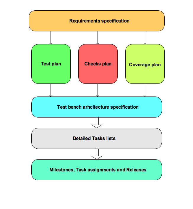
    Get clear understanding of verification requirements. Create detailed technical plans first before getting into creating schedules and doing resource requirements evaluations. Schedules and resource allocation should be based on technical plan.  Jumping in directly into it creates inaccurate forecast for both schedules and resources.

    A technical plan is two key sub-items a verification plan and test bench architecture specification.


    Verification planning flow
    Verification planning flow

    Read about the details of each of the steps of the planning in the links pointed below.

    Key to success, while creating the initial technical plans is to forget about the deadlines and resources. Technical plans and execution are two different activities. These should not be mixed with each other. One should follow “dream big, execute small” philosophy.

    Theoretically enumerate all the requirements assuming infinite time and resources. Execution of the same can be driven by priorities and resources later. Cutting corners in creating technical plans will keep project execution on toes all the time for very long time. Any time saved by cutting corners is not really worth it. Thinking does not really take as much time as execution takes. There is always option to prioritize items later.

    All the plans be it test plan, checks plan, coverage plan or tasks lists should be capable of adapting to dynamically changing requirements and allow the effective teamwork anchored around them.

  • UVM dissection – All class hiearchy

    UVM code reuse is predominantly a framework reuse model. It’s effective application requires certain level of source code exposure as discussed in the “UVM dissection – Why it’s needed?

    In order to dissect the UVM source code certain aids were thought to be useful. First one was the number of files and classes present in UVM. It was discussed in the UVM deep dive – statistics.

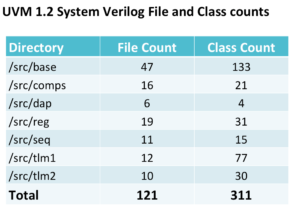
    There are 311 System Verilog classes in UVM 1.2 implementation. Not all of them are user-exposed classes. Now to make any sense of these many classes a complete class hierarchy would be useful. This would serve as navigation map for browsing the code.

    UVM class reference does provide the individual class hierarchy but all the class hierarchy in a single picture is missing. This is important to understand the bigger picture.

    Although there have been some pictures of class hierarchy beyond single class as part of UVM presentations but most of them are focused on certain classes under discussion. For instance one of the popular class, which has more complete hierarchy available is uvm_object. Have you wondered why is the uvm_object a popular one? Because its second highest fertile class with 39 children and its parent to some important classes.

    What is benefit of bigger picture? Just see one for yourself. UVM phasing is one of tricky concepts. Which phases are bottom up? Which phases are top down? What are the total phases? Following picture shows that. The string in the parenthesis is the directory in which the class is located in the source code.

    Mind map is a great tool for viewing and analyzing the hierarchical information. A UVM class hierarchy mind map showing all UVM class relations in single snapshot is shown below. On the left side of this mind map are UVM classes that are not derived from any other classes. Right side of the mind map is classes that are derived from different base classes. Following one is snapshot of mind map(save the image and zoom in). Interactive mind map can be accessed online here. It has limited capabilities supported by vendor mindmup.

    Best mind map browsing experience is with the mind map tool on your machine with all capabilities. Searching and filtering can make it easy to find the information you are looking for. Freemind is one of the freeware for browsing mind maps. Email me , I can send you the Freemind mind map(uvm_head_on.mm) file.

    Please comment or email if you think any other way of viewing UVM class information can aid your dissection better.

    Happy deep dive, see you on other side !

  • UVM dissection – statistics

    UVM code reuse is predominantly a framework reuse model. It’s effective application requires certain level of source code exposure as discussed in the  “UVM dissection – Why it’s needed?

    First level of dissection is some vanity statistics. Statistics provides the idea about the scale. When the magic “uvm_pkg” is imported in verification environment, what do I get? Has this question ever crossed your mind? One can say why do I care? It’s tradition, we just include and move on with the business of verification.

    The reason we need to care is there is price to be paid. UVM source code may be free. But simulator licenses are not free. Compute farms where the simulations are being run are not free. I can enumerate many others that are not free but let’s just stop here. Point is UVM also needs to be compiled and simulated too. That costs simulator licenses and computer farms.

    UVM Class statistics
    UVM Class statistics

    UVM uses the DPI written in C/C++. I am not including the DPI details here at the moment. Lets focus from the System Verilog part of it. When you include the magic uvm_pkg, as of UVM 1.2 implementation you are getting 121 files and 311 classes. Your verification environment may have 10 files and 20 classes but just by including the uvm_pkg your class count would be shot up by 311. Note that UVM needs compilation. See your compile log file. When the simulation is started these classes will have to be loaded. Look at the class hierarchy shown in the interactive debuggers.

    Don’t worry about it. With the growth in the compute power, Focus has been on the human effort minimization and not the computer resource optimization as a first priority. But the point is, since you are paying price by including uvm_pkg make it count by extracting the best productivity boost out of it.

    Next level of dissection is all UVM dissection – class hierarchy.


  • UVM dissection – Why it’s needed?

    Universal verification methodology(UVM) has become ubiquitous with functional verification but it’s not the complete picture of the functional verification. It’s hard to find any recent verification environment built without using Universal verification methodology(UVM). 

    Most verification engineers have seen UVM as told by others. I mean through the documentation, tutorials and examples. Very few engineers really take a peek at the UVM source code. UVM source code exploration may not be possible to beginners but it’s required to grow into an advanced user.

    Good part of UVM is that it’s source code is readily available. One can argue that I am not a UVM developer, I am just a user and why should I look into the source code?

    To answer this question we need to understand the code reuse models. See where UVM code reuse fits in and what are requirements of effective code reuse.

    Code reuse paradigm can be divided broadly into three types. There is also mix of these possible.

    • Reuse the code as a Product
    • Reuse the code as a Service
    • Reuse the code as a Framework

    Code reuse model as product  

    Code reuse model as product is using the code as a complete application. Not in bits and pieces. When we use the code as a product we just care about the user interface it offers.

    For example, consider a photo viewer application. All we care about is how we can open and navigate the photos. We don’t even care about the programming language in which it’s implemented.

    In the reuse model as product, user enters the product and product takes care of user’s requirements. User does not have to worry much about it.

    Code reuse model as service  

    Code reuse model as service is using the services offered by the reusable code in different user applications. Typically the “service provider” code is integrated in the “service user” to create an end application.

    In order to integrate service provider, user has to understand the services offered, interface, language of implementation, performance and its compatibility with user development platform. For example, consider simple utility algorithms library.  Let’s consider a simple service as sorting numbers. User may have to choose between algorithms offered based on its memory and compute time tradeoffs.

    Service provider is entering the end application user is building. So user will have to take care of correct integration. In code reuse model as service, user needs to look deeper into service provider code than the code reused in product reuse model.

    Code reuse model as framework  

    Code reuse model as framework is reusing the code skeleton for building applications of certain types. Framework reuse mainly offers the streamlining of application structure.

    Frameworks are customizable.  User of framework needs to understand various frameworks available,  it’s fit for the problem,  language of its implementation, and its compatibility with user development platform.

    In framework reuse model, user code enters into the framework. Framework is customized to fit application requirements. Framework reuses are tougher than the first two-reuse models. More than the code reuse framework reuse is about incorporating the best-known practices.

    Code reuse model for UVM is…

    UVM is a framework reuse model.

    UVM offers framework for building clean and maintainable verification environments quickly. UVM by itself does not do any verification but it’s just enabler for building test benches.

    In order to use UVM effectively dissection is necessary. Some aids are needed to help with this dissection. Lets look at those aids in next few posts.

    Aiding dissection:

  • Functional verification – A Bigger picture

    What is Functional verification?

    Universal verification methodology (UVM) and System Verilog (SV) was the answer I got. Verification methodology and high-level verification language (HVL) are playing a key role but they are not the functional verification.

    This is perception, especially the new engineers coming in have. Totally agree, SV and UVM have made a big impact on the productivity of the functional verification. But they are just enablers. They are means to an end but not the end itself. At times enablers get glorified so much that the final destination itself is forgotten.

    This happens due to lack of visibility into bigger picture. A clean bigger picture of functional verification will make it possible to develop right sense of proportion to each part. Functional verification is much beyond verification methodology and HVL.

    Following presentation is a quick tour, especially helpful for the new entrants to area of functional verification.

    Agilesoc voicing similar concern much early on in UVM is not a methodology. Test and Verification‘s Mike Bartley presentation on trends in verification slide#33 says “A UVM TB can only be as good as your verification plan!”.

    If verification methodology and HVL were the superpowers of functional verification then all the projects done using it should have been successful – Right?  Unfortunately, many verification projects even when using the SV and UVM (also other verification methodologies as well) have failed to meet their objectives.

    UVM and SV are powerful tools. But one needs to understand the bigger picture and fundamentals well to extract the maximum performance from HVL and verification methodologies.

    Please notes it not a campaign against HVL and verification methodologies. It’s an attempt to put them in the right perspective. Provide them the place they deserve in the bigger picture of the functional verification.

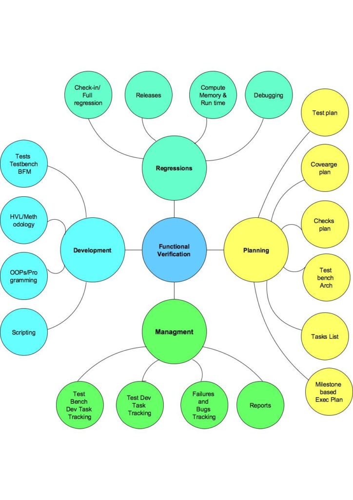
    One simplified view of the big picture of the functional verification is following.

    VS_Blog_Verification_Scope_1.docx-.jpg
    Functional verification – a bigger picture

    Functional verification is made up four major activities. Planning, Development, Regression and Management. First three activities planning, development and regression are phases of the verification project. These phases do not end completely but major focus shifts from phase to phase during the course of the project. Functional verification starts off  with the planning phase. There on for every milestone is executed as combination of development phase and regression phase. Fourth activity is managing the three phases for high quality and productivity.

    Planning phase is mainly putting in together the verification plan consisting of test plan, checks plan and coverage plan. Using the verification plan to define the test bench architecture. Using both of the build detailed tasks lists and milestones to prepare for the development.

    Development phase is about the execution of the tasks lists created during the planning phase. Development phase consists of building test bench, bus functional models, writing tests, coding functional coverage and getting the sanity tests passing. This where the HVL and Verification methodologies play a dominant role. But note that his just one of three activities.

    Regression phase is the climax of the verification. Regression phase is mainly getting all the tests and test variants passing. Filing the bugs and validating the fixes. Achieving the desired the desired passing rate and convergence on the coverage.

    Managing each of these phases has its own challenges. There are six parameters identified for ensuring quality and productivity. They are Clarity, People, Metrics, Tracking, Review and Closure.Each of these six parameters manifest differently in each of these phases.

    Anything more to add?

  • Execution and Closure of the error injection verification

    Execution and closure of error injection verification is the last step. Ordering the execution of the verification plan with the following tips can help improve the effectiveness of execution.

    If you have reached this step it means, you have followed the “Error injection scenario enumeration thought process”. The scenarios have been prioritized as per the “Definition of the sensible error handling verification plan”. The BFM selected meets the “Error injection capabilities of bus functional models”. The tests have been written following guidelines of “Structuring the error injection tests”.

    It’s assumed that normal operation verification has achieved certain level of stability before starting the error injection verification.

    Test execution closure

    Error injection tests execution should start with the directed tests. Directed tests are simpler to bring up and debug. It’s generally a good idea to go with “width first” approach unless and until there are specific demands. Width first means exercise all the error injection types in directed mode before jumping in to exercising it in the constrained random mode. Width first allows catching many issues and gives enough time for designers to fix the issues. Constrained random will take longer duration of time to exercise and clean it up. Its goes deeper into each of the error injection types.

    After the directed tests are clean it’s then advisable to jump into the constrained random tests exercising.  The numbers of seeds have to be decided differently based on the error injection type. Finding bugs can drive the number of seeds selection initially but it can later settle down to minimum seeds to achieve the desired functional coverage.

    Functional coverage closure

    Basic functional coverage for error injection has to be driven by the error configuration. Error injection types have to cover for both the single and multiple error injections simultaneously. Corruption variations per field and sequence will have to be separately covered.

    Cross coverage has to be defined for the following:

    • Error types, which are applicable to multiple protocol data unit types. These have to be covered with the right type of cross coverage between the error injection type and protocol data unit type
    • Error types, which are applicable to both transmit and receive side. So those have to be covered by crossing the direction with the error type

    Be cautious with the cross creations. It’s easy to create the cross but difficult to cover. So keep the cross restricted to relevant error injections.

    Error configuration error type coverage can be met by the directed error injection tests. Whereas the variations of the corruptions and cross coverage is best covered using the constrained random tests.

    Summary

    Ideal order for the error injection test execution is following:

    • Independently for transmit and receive side
    • Directed tests exercising single error for all the selected error injection types
    • Constrained random tests exercising single error for all the selected error injection types independently for transmit and receive side
    • Directed tests exercising selected multiple error combinations independently for transmit and receive side
    • Constrained random tests exercising selected multiple error combinations independently for transmit and receive side
    • Simultaneous error injection on both transmit and receive side  
    • Constrained random tests exercising single error for all the selected error injection types independently for transmit and receive side
    • Constrained random tests exercising selected multiple error combinations independently for transmit and receive side
  • Structuring the error injection tests

    Error injection being a complex feature demands focus and cleanliness in all the areas. Also the error injection can easily contribute to about  30–40 % of the total tests. This is not a small number.

    Tests written for the error injection should be well structured for two primary reasons. First in order to make tests easy to debug and second improve the reuse of the code across the tests. Considering the total contribution of the error injection tests good reuse can reduce the test development effort.

    Some common characteristics of the tests, apply to error injection tests as well

    Error injection test stimulus and response checking

    One key point, which is, often ignored, is data traffic being a part of every test. Make sure there is a data traffic flowing through before the error injection, after the error injection and after recovery sequence completion. This is very important because we are building the protocol for communication of data. So all the tests need to exercise data traffic with whatever else they are doing. Because whatever else they are doing is to aid the reliable and efficient data communication.

    Error injection tests will be characterized by:

    • Stimulus containing
      • Type of the error injection being exercised
      • Trigger for recovery
    • Checks to be performed on DUT
      • FSM state
      • Interrupts and configuration status registers
      • Recovery sequence

    Error injection tests directed versus constrained random selection

    Now the key thing is deciding which tests should be directed and which should be constrained random tests. The errors that have high probability of occurrence and have error recovery sequence implemented in the hardware are clear candidates for the constrained random verification. This is because you want to exercise them rigorously. The scenarios, which have low probability of occurrence and software based recovery sequences are fine to be exercised with the directed tests. Ideally everything should be constrained random if you have the luxury of schedule and resources.

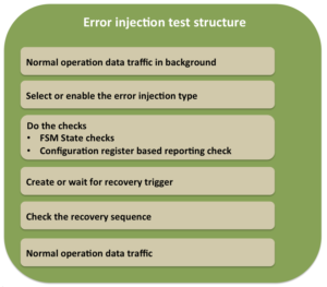
    Error injection test typical structure

    Data traffic generation can use existing sequences, which have been developed for the normal operation verification. Make sure not to jump into error injection verification unless there is some stability in the normal operation verification is achieved.

    Error injection test structure
    Error injection test structure

    Setup the error injection in either directed or constrained random manner. In the directed cases, the tests itself will create the error configuration with the specific error injection type to be exercised. It will program the same to BFM. In the constrained random tests the weights are programmed for the errors to be enabled.

    After the error injection do the required checks. The checks will have to check if there is any error reporting associated. All the errors detected may not be reported but for the ones reported will have to be typically checked by reading the configuration registers. There may be requirements to check the states of some key finite state machines (FSM). In fact error injection tests may be contributing to the FSM functional coverage as well.

    After the reporting and state checks, the recovery sequence will have to be checked. The recovery sequence trigger has to be clearly identified. The recovery trigger can be

    • Corrupted protocol data unit itself
    • Timeout in case of missing protocol data units
    • Protocol data unit following the corrupted protocol data unit
    • Other

    Recovery mechanism could be built in to hardware or initiated by the higher-level application.  Typically when it’s handled by the higher-level application it will be some form of reset. Whereas when it’s handled by hardware it will use sequence of the predefined protocol data units. Recovery sequence is checked by the BFM.

    After recovery sequence check completion, any additional checks as to clearing of some the status registers or state-indicating readiness for normal operation may have to be checked.

    After completion of recovery sequence do not forget adding data traffic before calling it an end of test.

    Some optimizations while writing the tests are possible. Based on the commonality of the recovery mechanism it may be possible to combine multiple error injections in a single test file. In such tests, the type of error to be exercised could be passed through the command line. This will minimize the number of the tests to be maintained.

  • Error injection implementation in Bus functional models (BFM)

    Error injection is a complex area in all its related dimensions. Supporting it in bus functional models(BFM) is also not an exception. Care has to exercised, if not it can easily create mess. Danger is it will affect the stability of the bus functional model in all areas.

    Keep in mind, BFM’s default mode of operation will be normal operation. Verification will use normal operation mode for 70 % of time and 30 % time it will use it for error injection.

    Error injection support implementation in BFMs, is like swimming against the current  of river. Bus functional model architecture has these contradictory requirements to be fulfilled. On one hand, they have to model the normal operation and  an on other error injection.  Both have to be housed together in the same enclosure. Error injection is like living being with contagious disease and normal operation is like healthy living beings. Now if the error injection is not quarantined it will spread the disease to other parts of the BFM. Thus affecting the overall code stability of the BFM.

    We certainly don’t want the code that is used for the 70 % of the time to be affected by the code that’s used for the 30 %.

    In next few sections let’s look at some of the ways to cleanly structure the error injection implementation in BFM.

    We have already seen the requirements for the error injection support from BFM in the “Error injection capabilities of bus functional models”.

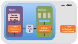
    Error injection support is made up of three major functional areas:

    1. Randomization of the error configuration
    2. Applying the error configuration to the protocol data unit
    3. Checking the response from the DUT on the line


    Error injection implementation in BFM
    Error injection implementation in BFM

    1. Error configuration randomization

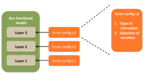
    Error configuration contains information about the type of corruption and selection among the variations for the corruptions. Field corruption variations consist of  different illegal values for a selected field. Sequence corruption variations consist of different possible protocol data units. Typically a error configuration per protocol data unit is desired.

    First level of quarantining is avoiding merging of error configuration and the respective protocol data unit class. Eve when it may seems tempting to do so.

    Every layer should have it’s own error configuration. It should not be mixed with the other layer. Some layer can have multiple error configurations, if it supports multiple distinct functionalities. A typical link layer for example would support three major functional areas, link initialization, link layer control and supporting data flow of upper layer. These are clearly three different areas and it’s okay to have three different error configurations to control the error injection in respective areas.

    Properties representing type of corruption and selection among variations of corruptions, in the error configuration class will have to be random and constrained to correct values.  In order for the constraints to be implemented correctly the respective layer configuration and state information is also required. The layer configuration is required to tune the the randomization as per the DUT configuration. The definition of the legal range is typically dependent on the configuration of the system. The definition of the legal sequence is typically dependent on the state. So the correct the corrupted value generation will be dependent on both of these. Error configuration should have access to the corresponding protocol layer’s configuration and state objects as well.

    Apart from that sometimes layers may operate very closely. In such case the error injection in one the layer can have effects on another layer. This may appear like breaking the abstraction of layering but note that it’s protocol design. So in such cases the error injection information about related layers will have to be exchanged with each other.

    The protocol data unit corrupted should hold the error configuration with which its corrupted. This will ease the debug process.

    Error configuration should also have ability to generate the different errors based on the weights specified for different error types.

    Error configuration randomization should be able to generate the one of the valid error types and select the one of the correct illegal variations for the injection, given the corresponding protocol data unit, layer’s configuration, layer’s state and optionally the weights for the different error types. Setting up these constraints is not a simple task. It takes few iterations to settle down. Key to getting right quickly is, in case of failures do not do point thinking, go after the root cause. In case of error injection all problems need due attention. Either at the point of problem or later they will claim their share of time and effort. So better give it early and close it right.

    2. Error configuration application

    Applying error configuration means executing the information present in it. If its field corruption, the corresponding field in the protocol data unit will be overwritten with its corresponding corrupted value generated in the error configuration. If it’s the sequence corruption the current protocol data unit will be replaced with the corrupted protocol data unit. At times this could be null. Which is meant for creating the missing protocol  data units scenarios.

    Now applying the error configuration may sound simple. Yes it is simple. Challenge is in selecting the right point for applying it in data flow path. It may sound very tempting to distribute it at various points in your data flow paths. This is strict no. Do not puncture the normal operation data flow path at multiple places. Minimize the point of corruptions. Best is single point of corruption. Pick a point in data flow where all the protocol data units of layer pass through and corrupt it at only this point. This helps to keep this part of the error injection logic quarantined to a specific point.

    At times it may not be possible to restrict it to single point. Especially when the layer has multiple distinct major functionalities. Link layer for example. It will contain the initialization, layer control sequences and data flow from upper layer. All these three are distinct functionalities and may need a different point of error configuration application. In such cases one point per each functional area is appropriate. Bottom line is keep these points to as minimum and clean as possible.

    3. Error response checking

    The response from the DUT for the error injection needs to be checked at two interface:

    • Recovery: For some errors are recovered in hardware driven recovery protocol. This is accomplished by initiating protocol defined recovery sequence on the line. This will be visible to BFM.
    • Reporting: The error detected will have to be reported to application. Sometimes internal statistics counters maintained in the hardware will have to be updated. This typically accomplished with the interrupts and status registers. This will not be directly visible to BFM. This has to be checked by tests or test bench.  

    Recovery mechanism action will be visible to the BFM. So BFM will have to set up expectations to check if this recovery sequence has been triggered. For the error injection done from the transmit side of the BFM, the expectations for checking the recovery sequence will have to be passed to receive side. Its best to setup a tracker queues through which the transmitter can pass the information about the expectations on the response with the receive side. As indicated the corrupted protocol data units must contain the error configuration associated with it. This protocol data unit will have to be passed to receiver for checking error response.

    On receive side whenever it finds the tracker entries that have the protocol data units with valid error configurations, checking should be implemented as separately as possible from normal operation checking. Checking logic is one of the parts of the logic where clean quarantining can be challenging. This is because of the reuse of checking logic between the normal operation and error response checking.  

    The expected response also being set up  as a part of the error configuration itself is a good idea. This provides the flexibility for tests to tune the checking as per slight variations in the DUT implementation, when required.

    Key to successful implementation of the error injection support is to keep it quarantined as much as possible from the normal operation data path. Allow as much flexibility in this logic as possible in both stimulus generation and especially in response checking to accommodate the unforeseen scenarios.

    Which can be many !


  • Error injection capabilities of bus functional models

    This blog will discuss what are the expected capabilities from the bus functional models (BFM) for the error injection support.

    Before we jump into details of support required in the bus functional models, in the post “Error injection scenario enumeration thought process” we understood that the error injection is primarily modeling the manifestations of imperfections of physical line. Now one may question, why not just model it like that?  That is model a wire to do random corruptions of the data passing through it. Simple solution, why go add error injection capability in the bus functional models?

    Answer may seem bit too obvious for veterans but for the benefit of newcomers bringing this point up. Good news is, yes you can. It will create the valid scenarios as well. But remember in the functional verification we want all the cases that real life usage can create but in the controlled environment. With the random data corruption if we want to specifically corrupt some field of a protocol data unit, it will become tedious to do so. Also it’s not just sufficient to corrupt we also need to check if it’s handled correctly by DUT.

    This means, test will have to figure out when is this transaction going out by decoding data going out on the physical line, corrupt the right data and then pass the information about corruption to BFM, if its implementing any checks.  It’s not impossible but it will demand more effort and process is error prone. To overcome this, control is desired at higher level of abstraction. This means test should be able to indicate at higher level to corrupt a specific field of specific protocol data unit. This type of interface is critical to close the error injection functional verification. That’s reason it’s modeled in the bus functional models instead of the physical lines.

    Now that we are clear why we need the error injection capabilities in the bus functional model let’s explore what should we expect from it?

    Functional requirements for error injection:

    Bus functional model should be able to meet the test case requirements identified following thought process outlined in the blog “Error injection scenario enumeration thought process”. It should support :

    • BFM Transmit side error injection
    • BFM Receive side error injection
    • For multi layer protocol, should allow error injection in every layer
    • Allow single and multiple error injection based on requirement
    • Allow back-to-back error injection based on requirement
    • Error response checking  for line side response should be built-in
    • Allow simultaneous error injections in both directions

    This blog will assume bus functional models implemented using object oriented programming interface. It’s assumed primarily due to ease of information abstraction. If the abstraction can be achieved through other mechanisms the concepts will still hold true.

    Error injection interface of BFM
    Error injection interface of BFM

    BFM’s Error injection interface

    Before we jump into the interface details, let’s understand what needs to be communicated to BFM’s for doing error injection.

    Error injection requires specifying two types of information:

    • Type of error injection  
      • Field or sequence error injection
    • Selection of possible variations
      • For field corruption the corrupted value of the field to be used for corruption
      • For sequence corruption the protocol data unit replacements to be used for corrupting the sequence

    Both of these information together is typically abstracted as error configuration.

    Where should this error configuration information be specified?

    In multi layer protocol every layer will have its protocol data unit. Each protocol data unit should support field and sequence corruptions. Typically this is protocol data unit is modeled using a class. This class will contain all the fields as the class properties.

    There are two possibilities to specify the error configuration related to this protocol data unit:

    1. Implement the error configuration in the same class as the protocol data unit

    2. Implement the error configuration in a separate class

    It’s recommended to choose the second approach of implementing the separate class for error configuration. For simpler protocols it may not make big difference but for the complex protocol it will yield good returns by it’s cleanliness of division.

    How to program error configuration in BFM?

    BFM should provide the APIs for programming this error configuration. As per the error configuration specification BFM should corrupt the selected protocol data unit.

    This could be separate API or error configurations can be attached with the protocol data unit to be corrupted. In case of separate API it’s important to also specify the protocol data unit to be selected for the corruption.

    How  do we control the selection of the protocol data unit to be corrupted?

    There are two popular approaches possible:

    1. BFM provides the protocol data unit through call back. Test attaches the error configuration to that specific protocol data unit and then BFM injects the specified error as per the error configuration
    2. BFM provides simple API as to corrupt the next protocol data unit. To detect if the next protocol data unit is the transaction of interest BFM provides the events

    If the second approach is used the test code flow will look linear. Whereas due to callback usages in the first approach the code flow will not look linear. Linear code are simple to understand and maintain.  Both the approaches will accomplish the objective.

    In multi layer protocol it’s advisable to keep the error configuration for individual layers separate. This keeps the implementation clean and allows scope for incorporating the expansion of the protocol in future.

    Directed vs Constrained random error injection

    Error injection should allow exercising error injection in both of the following modes:

    • Directed error injection
    • Constrained random error injection

    Directed error injection should allow creation of any error injection scenario. In order to be able to create very specific scenarios the test needs to understand what is happening inside the bus functional models. The state and various events about the internals of the BFM should be provided to the test through the events and callbacks. Through these events, callbacks or any other mechanism the test should be able to achieve the necessary synchronization and then exercise the error injection to create the specific scenario of interest. In this case test generate traffic and uses the error configuration to specify the error to be injected.

    Constrained random error injection is kind of the hands free mode of the operations. In this case test would only generate the traffic and BFM would do constrained random error injection of enabled error injections. One of the effective control for error injection enabling in constrained random mode is through percentage specification.  BFM should allow the specification of percentages for either any specific error or category of errors.  This would allow user to mix different types of the errors with the different weights as per the requirement. Now it’s important to do the selected errors in constrained error injection. Typically the best to consider the innermost circle of the errors indicated in the “Definition of the sensible error handling verification plan” for constrained random error injection.

    Debugging help

    Error injection debugs can get really crazy. Logging is one of the key interfaces through which the BFM’s provide the debug information.

    BFM should be able to clearly identify following through the logging interface:

    • Whether the protocol data unit logged is corrupted or not
    • If corrupted corrupted the details of the error configuration associated with the corruption
    • In case of corruption it’s better to provide the information about the uncorrupted protocol data unit as well along with the corrupted protocol data unit. This eases the analysis in many debugs.

    In the course of the error injection there is high probability that the DUT’s will misbehave. This would be caught by the checks implemented in the BFM. The checks should have meaningful message to guide the debug in right direction.

    Flexibility in error response checking

    Certain error injection scenarios can  result in multiple possible responses from the DUT. These possibilities could manifest as different response or missing response or additional protocol data units from DUT.

    Error configuration should allow user to override the expected responses. By default it can implement most likely response but it should provide the flexibility to specify a different response for checking.

    Also BFM should have capabilities to downgrade certain checks. This is not to be used as a  long term solution but for work around during the DUT development. In certain cases, it may be interesting to see how the DUT behaves further beyond a check failure for understanding the scenario better. Check downgrading will be useful in this case as well.