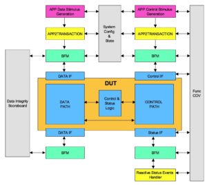
Test bench is an abstracted model of the application world surrounding the DUT. Test bench also can be thought as a layer of abstraction that translates from application level to transaction level. BFM, one of the major components of the test bench translates the transaction to physical level to be consumed by the DUT.
All the verification components are instanced and stitched together in the test bench. One side of the test bench interfaces with the DUT while the other side interfaces to the test.
Wear verification goggle to see test bench better.
These test bench components will have to do two things:
1. Program the application level stimulus in to DUT or BFM
2. DUT responses checked at different level of abstraction based on its applicability
Test bench architecture
Test bench is divided into the following functional areas:
- Stimulus generation
- Common to stimulus generation and response checks
- Response checks
- End of test (EoT)
Test bench configuration
Configurations allow configurability of the test bench. There are two types of configurations. Structural and functional configuration.
Structural configuration provides the configurability of the structure of the test bench. Typically this is done at the start of the simulation. Configurability could be presence or absence of certain interfaces, number of instances of certain interface or design module, Widths of various interfaces etc
Functional configuration will provide the configurability of the functionality. Most of the interface specific functional configurability is expected to be handled by the BFMs. Test bench functional configurability will provide the configurability for application level stimulus generation. For example a specific interface being enabled for traffic generation or certain type of traffic generation disabled for certain other interfaces. Configurability for the test bench components other than BFMs. For example disabling scoreboard or configuring the interrupt polling frequency or address map for the memory model.
It’s better to keep both the structural and functional configuration separate. Typically the configurations are designed to be global objects available to all the test bench components.
Constrained random stimulus generation
Constrained random stimulus generation at the application level is one the key functionalities of the test bench. There are two key categories of the stimulus generation. First one is the data traffic stimulus generation and second is control event stimulus generation.
Data traffic stimulus generation mainly targets the DUT’s data path. Typically it’s relatively simpler to implement than control event stimulus generation. Data traffic stimulus generation should take care of generating all the possible types of data traffic and making sure all the programmable variables associated with the data traffic are being exercised to their defined legal range.
Control event stimulus generation mainly targets the DUT’s control path. These control events alter the data flow. For example consider low power entry and exit scenario of serial communication link. Thought process for control event generation should be no different compared to data traffic stimulus generation. This point is made in the context of flexibility. Control event stimulus generation should be as flexible as data traffic stimulus generation. Its secondary whether the verification ends up enabling and using it in its full glory. Structure should be designed such that the flexibility is not compromised.
Constraints are key part of the stimulus generation implementation. Remember to randomize as many variables as possible but all randomizations should be test controllable. Deep code buried randomization which are not controllable by test are dangerous. It should not be done.
Application level to transaction level translations
This is another major functionality for the test bench. To make this more clear let’s take an example of data transfer using DMA. Basic stimulus generation is data size and random data to be transferred matching size. DUT would access it through the system memory by fetching data using DMA. For this stimulus to execute data storage space should be allocated in system memory model. Address point and size should be programmed in the DUT. This programming can be through a system bus. Test bench is expected to allocate memory for this stimulus and program the DUT by generating the appropriate transactions on the system bus. Application level stimulus here was the size and random data matching the size. Whereas stimulating DUT with this stimulus requires multiple steps as outlined above which forms the translation logic.
Depending upon complexity of the translation test bench can also implement it in multiple layers. Each layer doing a part of translation task. Translation logic itself may have certain other control variables which might need randomization. The translation layers variable randomization associated with the stimulus should be made part of the same high level stimulus.
Scoreboards of different types
Scoreboards typically do a matching check on related events that cross multiple interfaces. At least two. A transaction left from one interface has it reached the other interface correctly? This type of checks are implemented in the scoreboard.
Why BFMs themselves do not implement this check as well?
BFM will be able to do protocol checks localized to a specific interface they are handling. They will not be able to check something which requires knowledge of other interfaces. Anything that requires knowledge of multiple interfaces in order to do the check is handled by the scoreboards in the test bench.
Scoreboards are the components which are most often used for doing data integrity checks across interfaces. Let’s take a example of a simple protocol bridge like USB to UART protocol converter DUT. This DUT on one side will operate USB and on another side the UART. The individual UART and USB protocol checks will be implemented by the respective BFMs. The data integrity check on the traffic passing through cannot be checked by any single BFM. That’s because the receiving BFM needs the knowledge of the reference data from the transmitted BFM. This is handled by the scoreboard. A scoreboard would gather data from the transmitter BFM which is golden data and compare it with the data received at the receiver BFM which is the actual data. Any discrepancy found will be flagged by the scoreboard as data integrity error.
Since individual BFMs are capable of doing the lower level protocol checks scoreboard need not be implement them. It’s only needed at the highest level. Ideal is the application level scoreboard.
Scoreboard concept need not only be limited to data integrity checking. Although that’s the most popular one. Interrupts for instance can be contributed due to variety of causes invoked by different interfaces and combination of the events triggered by different interfaces. This can be checked by building a interrupt scoreboard.
Any checks to be implemented by collecting information from multiple interfaces is to be handled by test bench. Scoreboard concept is one of the popular way to deal with it.
Memory models (Optional)
It’s hard to imagine a system without CPU. CPUs are everywhere in one form or another. System memory serves CPUs in two ways. First it stores the code and data executed by the CPU. Second it acts as a medium for sharing data between the CPU and peripherals.
This system memory in test bench is modeled using memory models. They are built around sparse memory concept. Memory models also need address map mangement services.
Memory address map management services should be able to support
- Carving out the regions of different attributes
- Dynamic allocation and deallocation of the memory
- Identify and support multiple sources of memory access
Register models (Optional)
Most of the DUTs interact with the software. Control and status interface of DUTs is implemented using the registers. Basic register verification requires their accessibility and attributes check. Here the focus is not on the functional aspects but the physical register logic structure implementation checks. The functional aspects of the registers have to be verified through various tests. The randomized test bench functional configuration is typically programmed into the registers to match the expected functional configuration.
Register abstraction model(RAL) is the way the design’s registers are abstracted in the test bench. This mainly serves two purposes. First it provides the abstraction to tests which shields them from address map changes or physical bus on which registers are accessible changes. Second these RAL model come built in with the certain tests for the checking the accessibility and attributes which are functionality independent.
BFMs for all the interfaces
Bus functional model(BFM)s are pillars of the test bench structure. That’s why it’s very important to have a high quality BFMs in the test bench. They are also the engines that power the test bench machinery. BFMs form a layer in test bench which converts the transaction level stimulus to physical stimulus to DUT and vice versa.
A BFM per physical interface is instanced. If there are multiple physical interfaces multiple BFMs would be instanced. BFM development is described here.
BFMs are instanced as per the test bench’s structural configuration. The test bench will connect the physical interface of the DUT to the correct BFM instance. The programmable interface of the BFM is used by the verification components of the test bench as well as tests.
Identifying a clean boundary between the BFM and test bench is a key. Its always advisable for test bench to define its own APIs for accessing the BFM functionality to keep to avoid getting tied down to BFM being used. This abstraction will enable to use the BFMs from the different vendors within the same test bench to gain high confidence over the verification.
End of test(EOT)
A good end of test implementation is very important. End of test consists of two components. First one is end of stimulus generation and second is end of stimulus execution.
Typically end of stimulus generation is determined by the test and end of stimulus execution is determined by the test bench. Test bench creates a common logic that can check with all the components to ensure that stimulus generated has been executed.
Both of these steps have to wait. Any wait has possibility to become endless. Global watchdog timer will have to be implemented as part of EOT to guard against infinite wait. If EOT does not complete within the configured highest time the test is declared as hung and should be terminated.
For test to end successfully both of these must complete successfully. Note that successful end of test does not mean test has passed. It means test has completed to end of its execution.
Clocks and reset generation
The clocks and resets needed by the DUT are generated in the test bench. Any physical interface specific clocks are typically generated by the corresponding BFMs. It’s the set of the clocks that are not tied to any interfaces will have to be generated by the test bench. Jitter, skew or spread spectrum modeling of the clocks needs to be taken into consideration.
Multiple resets can be present based on the number of the clock and power domains. These resets may have reset sequencing requirements. Reset sequencing has to be carefully handled by the test bench. Possible delays and scenarios possible with the reset sequencing have to be thought out. This is extremely critical to avoid the dead chips.
Functional coverage model
Code coverage is necessary but not sufficient. Functional coverage is equally important to prove the scenarios and configurations we care for are covered thoroughly. Functional coverage model should implement both the types of functional coverage.
Functional coverage model is clean organization of what to sample and when to sample. A good functional coverage model can help prevent even famous bugs like pentium FDIV bug. Functional coverage model should be updated whenever bugs are found in uncovered area.
Did we miss any test bench component?