In any layered communication protocol, all the layers above physical layer will utilize some form of protocol data units to accomplish the protocol defined. Here for the simplicity, referring all the protocol data units as transactions.
Physical layer error injection requires a different thought process and will be covered in another blog. Following will focus on the higher layers transaction field error injection.
Transaction field error injection for higher layers of communication protocol will have to cover following. (more…)
A bidirectional interface have data traffic in two directions. As we had discussed in “Error handling verification of serial communication designs” the error handling is defined to cover the imperfections in the physical line. In bidirectional interface two physical lines are used for connecting both the directions. Thus effects of imperfections in physical line in both the directions should to be verified.
Execution and closure of error injection verification is the last step. Ordering the execution of the verification plan with the following tips can help improve the effectiveness of execution.
It’s assumed that normal operation verification has achieved certain level of stability before starting the error injection verification.
Test execution closure
Error injection tests execution should start with the directed tests. Directed tests are simpler to bring up and debug. It’s generally a good idea to go with “width first” approach unless and until there are specific demands. Width first means exercise all the error injection types in directed mode before jumping in to exercising it in the constrained random mode. Width first allows catching many issues and gives enough time for designers to fix the issues. Constrained random will take longer duration of time to exercise and clean it up. Its goes deeper into each of the error injection types.
After the directed tests are clean it’s then advisable to jump into the constrained random tests exercising. The numbers of seeds have to be decided differently based on the error injection type. Finding bugs can drive the number of seeds selection initially but it can later settle down to minimum seeds to achieve the desired functional coverage.
Functional coverage closure
Basic functional coverage for error injection has to be driven by the error configuration. Error injection types have to cover for both the single and multiple error injections simultaneously. Corruption variations per field and sequence will have to be separately covered.
Cross coverage has to be defined for the following:
Error types, which are applicable to multiple protocol data unit types. These have to be covered with the right type of cross coverage between the error injection type and protocol data unit type
Error types, which are applicable to both transmit and receive side. So those have to be covered by crossing the direction with the error type
Be cautious with the cross creations. It’s easy to create the cross but difficult to cover. So keep the cross restricted to relevant error injections.
Error configuration error type coverage can be met by the directed error injection tests. Whereas the variations of the corruptions and cross coverage is best covered using the constrained random tests.
Summary
Ideal order for the error injection test execution is following:
Independently for transmit and receive side
Directed tests exercising single error for all the selected error injection types
Constrained random tests exercising single error for all the selected error injection types independently for transmit and receive side
Directed tests exercising selected multiple error combinations independently for transmit and receive side
Constrained random tests exercising selected multiple error combinations independently for transmit and receive side
Simultaneous error injection on both transmit and receive side
Constrained random tests exercising single error for all the selected error injection types independently for transmit and receive side
Constrained random tests exercising selected multiple error combinations independently for transmit and receive side
Error injection being a complex feature demands focus and cleanliness in all the areas. Also the error injection can easily contribute to about 30–40 % of the total tests. This is not a small number.
Tests written for the error injection should be well structured for two primary reasons. First in order to make tests easy to debug and second improve the reuse of the code across the tests. Considering the total contribution of the error injection tests good reuse can reduce the test development effort.
Some common characteristics of the tests, apply to error injection tests as well
Tests will be of two types: Directed tests, Constrained random tests
Error injection test stimulus and response checking
One key point, which is, often ignored, is data traffic being a part of every test. Make sure there is a data traffic flowing through before the error injection, after the error injection and after recovery sequence completion. This is very important because we are building the protocol for communication of data. So all the tests need to exercise data traffic with whatever else they are doing. Because whatever else they are doing is to aid the reliable and efficient data communication.
Error injection tests will be characterized by:
Stimulus containing
Type of the error injection being exercised
Trigger for recovery
Checks to be performed on DUT
FSM state
Interrupts and configuration status registers
Recovery sequence
Error injection tests directed versus constrained random selection
Now the key thing is deciding which tests should be directed and which should be constrained random tests. The errors that have high probability of occurrence and have error recovery sequence implemented in the hardware are clear candidates for the constrained random verification. This is because you want to exercise them rigorously. The scenarios, which have low probability of occurrence and software based recovery sequences are fine to be exercised with the directed tests. Ideally everything should be constrained random if you have the luxury of schedule and resources.
Error injection test typical structure
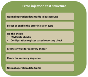
Data traffic generation can use existing sequences, which have been developed for the normal operation verification. Make sure not to jump into error injection verification unless there is some stability in the normal operation verification is achieved.
Error injection test structure
Setup the error injection in either directed or constrained random manner. In the directed cases, the tests itself will create the error configuration with the specific error injection type to be exercised. It will program the same to BFM. In the constrained random tests the weights are programmed for the errors to be enabled.
After the error injection do the required checks. The checks will have to check if there is any error reporting associated. All the errors detected may not be reported but for the ones reported will have to be typically checked by reading the configuration registers. There may be requirements to check the states of some key finite state machines (FSM). In fact error injection tests may be contributing to the FSM functional coverage as well.
After the reporting and state checks, the recovery sequence will have to be checked. The recovery sequence trigger has to be clearly identified. The recovery trigger can be
Corrupted protocol data unit itself
Timeout in case of missing protocol data units
Protocol data unit following the corrupted protocol data unit
Other
Recovery mechanism could be built in to hardware or initiated by the higher-level application. Typically when it’s handled by the higher-level application it will be some form of reset. Whereas when it’s handled by hardware it will use sequence of the predefined protocol data units. Recovery sequence is checked by the BFM.
After recovery sequence check completion, any additional checks as to clearing of some the status registers or state-indicating readiness for normal operation may have to be checked.
After completion of recovery sequence do not forget adding data traffic before calling it an end of test.
Some optimizations while writing the tests are possible. Based on the commonality of the recovery mechanism it may be possible to combine multiple error injections in a single test file. In such tests, the type of error to be exercised could be passed through the command line. This will minimize the number of the tests to be maintained.
Error injection is a complex area in all its related dimensions. Supporting it in bus functional models(BFM) is also not an exception. Care has to exercised, if not it can easily create mess. Danger is it will affect the stability of the bus functional model in all areas.
Keep in mind, BFM’s default mode of operation will be normal operation. Verification will use normal operation mode for 70 % of time and 30 % time it will use it for error injection.
Error injection support implementation in BFMs, is like swimming against the current of river. Bus functional model architecture has these contradictory requirements to be fulfilled. On one hand, they have to model the normal operation and an on other error injection. Both have to be housed together in the same enclosure. Error injection is like living being with contagious disease and normal operation is like healthy living beings. Now if the error injection is not quarantined it will spread the disease to other parts of the BFM. Thus affecting the overall code stability of the BFM.
We certainly don’t want the code that is used for the 70 % of the time to be affected by the code that’s used for the 30 %.
In next few sections let’s look at some of the ways to cleanly structure the error injection implementation in BFM.
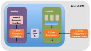
Error injection support is made up of three major functional areas:
Randomization of the error configuration
Applying the error configuration to the protocol data unit
Checking the response from the DUT on the line
Error injection implementation in BFM
1. Error configuration randomization
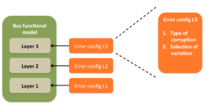
Error configuration contains information about the type of corruption and selection among the variations for the corruptions. Field corruption variations consist of different illegal values for a selected field. Sequence corruption variations consist of different possible protocol data units. Typically a error configuration per protocol data unit is desired.
First level of quarantining is avoiding merging of error configuration and the respective protocol data unit class. Eve when it may seems tempting to do so.
Every layer should have it’s own error configuration. It should not be mixed with the other layer. Some layer can have multiple error configurations, if it supports multiple distinct functionalities. A typical link layer for example would support three major functional areas, link initialization, link layer control and supporting data flow of upper layer. These are clearly three different areas and it’s okay to have three different error configurations to control the error injection in respective areas.
Properties representing type of corruption and selection among variations of corruptions, in the error configuration class will have to be random and constrained to correct values. In order for the constraints to be implemented correctly the respective layer configuration and state information is also required. The layer configuration is required to tune the the randomization as per the DUT configuration. The definition of the legal range is typically dependent on the configuration of the system. The definition of the legal sequence is typically dependent on the state. So the correct the corrupted value generation will be dependent on both of these. Error configuration should have access to the corresponding protocol layer’s configuration and state objects as well.
Apart from that sometimes layers may operate very closely. In such case the error injection in one the layer can have effects on another layer. This may appear like breaking the abstraction of layering but note that it’s protocol design. So in such cases the error injection information about related layers will have to be exchanged with each other.
The protocol data unit corrupted should hold the error configuration with which its corrupted. This will ease the debug process.
Error configuration should also have ability to generate the different errors based on the weights specified for different error types.
Error configuration randomization should be able to generate the one of the valid error types and select the one of the correct illegal variations for the injection, given the corresponding protocol data unit, layer’s configuration, layer’s state and optionally the weights for the different error types. Setting up these constraints is not a simple task. It takes few iterations to settle down. Key to getting right quickly is, in case of failures do not do point thinking, go after the root cause. In case of error injection all problems need due attention. Either at the point of problem or later they will claim their share of time and effort. So better give it early and close it right.
2. Error configuration application
Applying error configuration means executing the information present in it. If its field corruption, the corresponding field in the protocol data unit will be overwritten with its corresponding corrupted value generated in the error configuration. If it’s the sequence corruption the current protocol data unit will be replaced with the corrupted protocol data unit. At times this could be null. Which is meant for creating the missing protocol data units scenarios.
Now applying the error configuration may sound simple. Yes it is simple. Challenge is in selecting the right point for applying it in data flow path. It may sound very tempting to distribute it at various points in your data flow paths. This is strict no. Do not puncture the normal operation data flow path at multiple places. Minimize the point of corruptions. Best is single point of corruption. Pick a point in data flow where all the protocol data units of layer pass through and corrupt it at only this point. This helps to keep this part of the error injection logic quarantined to a specific point.
At times it may not be possible to restrict it to single point. Especially when the layer has multiple distinct major functionalities. Link layer for example. It will contain the initialization, layer control sequences and data flow from upper layer. All these three are distinct functionalities and may need a different point of error configuration application. In such cases one point per each functional area is appropriate. Bottom line is keep these points to as minimum and clean as possible.
3. Error response checking
The response from the DUT for the error injection needs to be checked at two interface:
Recovery: For some errors are recovered in hardware driven recovery protocol. This is accomplished by initiating protocol defined recovery sequence on the line. This will be visible to BFM.
Reporting: The error detected will have to be reported to application. Sometimes internal statistics counters maintained in the hardware will have to be updated. This typically accomplished with the interrupts and status registers. This will not be directly visible to BFM. This has to be checked by tests or test bench.
Recovery mechanism action will be visible to the BFM. So BFM will have to set up expectations to check if this recovery sequence has been triggered. For the error injection done from the transmit side of the BFM, the expectations for checking the recovery sequence will have to be passed to receive side. Its best to setup a tracker queues through which the transmitter can pass the information about the expectations on the response with the receive side. As indicated the corrupted protocol data units must contain the error configuration associated with it. This protocol data unit will have to be passed to receiver for checking error response.
On receive side whenever it finds the tracker entries that have the protocol data units with valid error configurations, checking should be implemented as separately as possible from normal operation checking. Checking logic is one of the parts of the logic where clean quarantining can be challenging. This is because of the reuse of checking logic between the normal operation and error response checking.
The expected response also being set up as a part of the error configuration itself is a good idea. This provides the flexibility for tests to tune the checking as per slight variations in the DUT implementation, when required.
Key to successful implementation of the error injection support is to keep it quarantined as much as possible from the normal operation data path. Allow as much flexibility in this logic as possible in both stimulus generation and especially in response checking to accommodate the unforeseen scenarios.
This blog will discuss what are the expected capabilities from the bus functional models (BFM) for the error injection support.
Before we jump into details of support required in the bus functional models, in the post “Error injection scenario enumeration thought process” we understood that the error injection is primarily modeling the manifestations of imperfections of physical line.Now one may question,why not just model it like that? That is model a wire to do random corruptions of the data passing through it. Simple solution, why go add error injection capability in the bus functional models?
Answer may seem bit too obvious for veterans but for the benefit of newcomers bringing this point up. Good news is, yes you can. It will create the valid scenarios as well. But remember in the functional verification we want all the cases that real life usage can create but in the controlled environment. With the random data corruption if we want to specifically corrupt some field of a protocol data unit, it will become tedious to do so. Also it’s not just sufficient to corrupt we also need to check if it’s handled correctly by DUT.
This means, test will have to figure out when is this transaction going out by decoding data going out on the physical line, corrupt the right data and then pass the information about corruption to BFM, if its implementing any checks. It’s not impossible but it will demand more effort and process is error prone. To overcome this, control is desired at higher level of abstraction. This means test should be able to indicate at higher level to corrupt a specific field of specific protocol data unit. This type of interface is critical to close the error injection functional verification. That’s reason it’s modeled in the bus functional models instead of the physical lines.
Now that we are clear why we need the error injection capabilities in the bus functional model let’s explore what should we expect from it?
For multi layer protocol, should allow error injection in every layer
Allow single and multiple error injection based on requirement
Allow back-to-back error injection based on requirement
Error response checking for line side response should be built-in
Allow simultaneous error injections in both directions
This blog will assume bus functional models implemented using object oriented programming interface. It’s assumed primarily due to ease of information abstraction. If the abstraction can be achieved through other mechanisms the concepts will still hold true.
Error injection interface of BFM
BFM’s Error injection interface
Before we jump into the interface details, let’s understand what needs to be communicated to BFM’s for doing error injection.
Error injection requires specifying two types of information:
Type of error injection
Field or sequence error injection
Selection of possible variations
For field corruption the corrupted value of the field to be used for corruption
For sequence corruption the protocol data unit replacements to be used for corrupting the sequence
Both of these information together is typically abstracted as error configuration.
Where should this error configuration information be specified?
In multi layer protocol every layer will have its protocol data unit. Each protocol data unit should support field and sequence corruptions. Typically this is protocol data unit is modeled using a class. This class will contain all the fields as the class properties.
There are two possibilities to specify the error configuration related to this protocol data unit:
1. Implement the error configuration in the same class as the protocol data unit
2. Implement the error configuration in a separate class
It’s recommended to choose the second approach of implementing the separate class for error configuration. For simpler protocols it may not make big difference but for the complex protocol it will yield good returns by it’s cleanliness of division.
How to program error configuration in BFM?
BFM should provide the APIs for programming this error configuration. As per the error configuration specification BFM should corrupt the selected protocol data unit.
This could be separate API or error configurations can be attached with the protocol data unit to be corrupted. In case of separate API it’s important to also specify the protocol data unit to be selected for the corruption.
How do we control the selection of the protocol data unit to be corrupted?
There are two popular approaches possible:
BFM provides the protocol data unit through call back. Test attaches the error configuration to that specific protocol data unit and then BFM injects the specified error as per the error configuration
BFM provides simple API as to corrupt the next protocol data unit. To detect if the next protocol data unit is the transaction of interest BFM provides the events
If the second approach is used the test code flow will look linear. Whereas due to callback usages in the first approach the code flow will not look linear. Linear code are simple to understand and maintain. Both the approaches will accomplish the objective.
In multi layer protocol it’s advisable to keep the error configuration for individual layers separate. This keeps the implementation clean and allows scope for incorporating the expansion of the protocol in future.
Directed vs Constrained random error injection
Error injection should allow exercising error injection in both of the following modes:
Directed error injection
Constrained random error injection
Directed error injection should allow creation of any error injection scenario. In order to be able to create very specific scenarios the test needs to understand what is happening inside the bus functional models. The state and various events about the internals of the BFM should be provided to the test through the events and callbacks. Through these events, callbacks or any other mechanism the test should be able to achieve the necessary synchronization and then exercise the error injection to create the specific scenario of interest. In this case test generate traffic and uses the error configuration to specify the error to be injected.
Constrained random error injection is kind of the hands free mode of the operations. In this case test would only generate the traffic and BFM would do constrained random error injection of enabled error injections. One of the effective control for error injection enabling in constrained random mode is through percentage specification. BFM should allow the specification of percentages for either any specific error or category of errors. This would allow user to mix different types of the errors with the different weights as per the requirement. Now it’s important to do the selected errors in constrained error injection. Typically the best to consider the innermost circle of the errors indicated in the “Definition of the sensible error handling verification plan” for constrained random error injection.
Debugging help
Error injection debugs can get really crazy. Logging is one of the key interfaces through which the BFM’s provide the debug information.
BFM should be able to clearly identify following through the logging interface:
Whether the protocol data unit logged is corrupted or not
If corrupted corrupted the details of the error configuration associated with the corruption
In case of corruption it’s better to provide the information about the uncorrupted protocol data unit as well along with the corrupted protocol data unit. This eases the analysis in many debugs.
In the course of the error injection there is high probability that the DUT’s will misbehave. This would be caught by the checks implemented in the BFM. The checks should have meaningful message to guide the debug in right direction.
Flexibility in error response checking
Certain error injection scenarios can result in multiple possible responses from the DUT. These possibilities could manifest as different response or missing response or additional protocol data units from DUT.
Error configuration should allow user to override the expected responses. By default it can implement most likely response but it should provide the flexibility to specify a different response for checking.
Also BFM should have capabilities to downgrade certain checks. This is not to be used as a long term solution but for work around during the DUT development. In certain cases, it may be interesting to see how the DUT behaves further beyond a check failure for understanding the scenario better. Check downgrading will be useful in this case as well.
This blog will focus on the error injection scenario enumeration thought process for bi-directional communication interface designs.
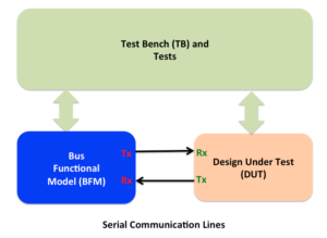
Simplest representation of the verification environment for bi-directional communication interface is shown below.
Bi-directional communication interface
Although there are unidirectional interfaces as well but they pose lesser challenge in terms of the error injection verification. The reason being there is no hardware recovery mechanism possible with the unidirectional interfaces. So they are not covered in this post.
Error injection scenario enumeration process may seem very discrete. When there is no clear thought process identified, one may randomly start listing the scenarios. This makes it difficult to judge whether all the key scenarios have been thought through. This confusion can lead to either bloated or inadequate listing.
Bloated list is a risk to schedule and inadequate list is risk to functionality of chip. Worst is bloated list with irrrelevant cases.
So, what is thought process that leads to effective enumeration of error injection scenarios?
This blog will show it. It will showcase: What are some of major parameters to be taken into consideration? How to establish the overall scope of error injection verification to enable assessing and questioning the completeness of listing?
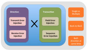
Following set theory based diagram is basis for building a three step process.
Error injection scenario enumeration thought process
Step #1: Populate sets
For bi-directional communication interface, there are two sets of key parameters. First is direction and second is transaction.
For field error injection element, list all the fields of the transaction that can be corrupted. For sequence error injection, list all the protocol violations possible which lead to sequence error injection.
Step #2: Transaction x Direction
First step is combination operations on two sets. First set containing direction and second set containing transactions. Here the word transaction means any generic protocol data units used by any layer.
All the combinations of these two sets should to be listed for unique error injection cases listing completeness.
Step#3: Additional variations
Once the unique error injection combinations are listed, each error injection case will have to be questioned with following questions
Are multiple errors simultaneously possible with this error injection case?
Are back-to-back errors possible with this error injection case?
Are simultaneous errors on both directions possible for this error injection case ?
Any YES answer will add additional cases which are combinations of the errors cases listed in the step#2.
This completes the process of enumeration. Let’s look into details as to what do these questions mean in detail.
Single versus Multiple Errors
Question here is, whether transaction should be injected with the single error or multiple errors?
Certain specifications do provide provision for dealing with the multiple errors taking place at the same time in a given transaction. If the specification allows it, then it must also define the priority in which the errors should be dealt with. In such cases it’s good idea to exercise the multiple errors taking place at the same time.
If it’s not defined, it should be considered as lower priority activity. Without the proper priority definition the receiver handling of the multiple errors can become ambiguous.
Back to back errors
Question here is, whether to allow the back-to-back errors?
In some of the protocols, after the first error is detected further error detection mechanism is disabled until the first step of the expected error recovery sequence is completed successfully. In such cases the further errors injected back-to-back beyond first error are ignored. So it may not add much value to verification and unnecessarily it will increase the complexity of the error injection logic implementation in the BFM.
If the receiver remains active beyond first error and responds differently to back-to-back errors then it’s effective to allow the back-to-back error injection. Although care should be exercised to ensure the right scenarios are allowed minimizing the complexity of the error injection logic implementation.
Decision on multiple errors at the same time and back-to-back error injection has significant implications on the BFM error injection complexity. So it should be carefully thought out.
Implementation
Transaction corruptions scenarios have to be thought out from both transmit and receive side. Many times the receive side corruption results in DUT seeing same response. Such cases can be grouped and covered by the single test case in implementation.
If multiple errors at same time, back-to-back errors and error injection simultaneously on both directions are allowed they should be implemented as additional variations of test cases rather than writing a test for each.
It’s very easy to identify loads of the error injection scenarios. Key is to focus on the right scenarios. As we have seen in the “Error handling verification of serial communication designs” failure to select the right error scenarios can lead to wastage of the valuable engineering resource and time on this activity.
Remember this the activity has high probability of going off track. A good plan is like a map that will keep it on track.
Next question, how do you know which scenarios are the right scenarios?
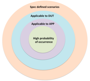
Definition of right scenarios for the error handling verification requires one to ask the following four questions and answer them:
Objective of these questions is to direct the thought process towards right scenarios by minimizing the noise and enabling right prioritization of the scenarios in the verification plan. Scenario with has more “Yes” answers are higher in relevance.
In next few paragraphs lets look at why each of these questions are important and how to use the answers of these questions to build right verification plan and how to use it for prioritization of execution.
1. Is the error scenario defined in the specification?
One can go wild and annotate exotic error injection scenarios. But if you are working on the standard specification, then first answer this question “Is the error scenario defined in the specification?”for every error injection scenario identified.
Our focus should be on meeting the intent of the specification first. Which means the error injection scenario identified is valid only if the error detection and action on error detection is specified in the specification.
If error is mentioned in the specification, check is any reporting or recovery action defined? Many cases specification may indicate the system state will become undefined when this error scenario takes place. These cases are not as important as the ones for which specifically reporting and recovery mechanism is defined. Design state becoming unknown cannot be verified meaningfully.
Scenarios, which lead to System state becoming undefined, are usually due to clear violation of specification in peer design implementation. One general rule of thumb to remember is error injection in communication protocols is meant for detecting, reporting and recovering errors due to imperfections in physical line. The physical line is unreliable. Protection for this unreliability is built through the error detection, reporting and optional recovery mechanisms. We do not have control over imperfect nature of physical line. Typically specifications do not intend to protect the flaws due to incorrect logic implementations. This is something expected to be done right.
Hence unless specifically requested the error scenarios for which the detection and action on detection is not defined in the specification should not be added in the verification plan.
On request by designers or architects, if such scenarios are added to verification plan it should be tagged as implementation specific error handling scenarios.
2. Does the DUT support this error scenario?
DUT may not implement all the features defined in the specification. In such cases although the error scenario defined in the specification, contains error detection, recovery and/or reporting but it may not be relevant to current DUT verification.
Make a list of the error scenarios for which answers to both of the above questions is YES. These are the scenarios applicable to current DUT.
Among these scenarios, prioritize the error scenarios that involve a complex detection and recovery mechanisms. One of the classic example of complex error scenarios is the one that involves retransmission based recovery logic. Retransmission logic can be fairly complicated. Typically it will also interact with the normal data transmission logic as well. So it’s better to exercise the complex logic and/or the logic that affects or touches multiple parts of the design early. This provides the designers ample time to fix issues found. Typically these fixes have higher potential to break other functionality, which is not directly touched. Such cases being verified early provide the time required for regressing effort involved. Goes without saying, prioritization becomes more effective by taking in to consideration the inputs from designers as well.
3. What is the impact of this error on end application?
Specification has defined it and DUT has implemented it. But the end application will never use the DUT in a mode where this specific error scenario is applicable. Such error scenarios can be deprioritized for the execution. Make list of the error scenarios that have answered YES to all three questions above.
Among these scenarios, prioritize based on impact of the error scenario for application. Some applications may have high tolerance for the error and for some other applications reliability, accessibility and serviceability (RAS) may be very critical. For example compare a desktop computer versus a server computer. For server computer RAS is of utmost importance. Based on the type of application, impact of each of the error scenario for targeted application should be evaluated for prioritization of the error injection cases for execution.
4. What is the probability of this error scenario happening in real life usage?
This is another angle that is useful in prioritizing the cases. Specification may have defined it, DUT has implemented it and it’s applicable for the end application usage but still some errors may have very low probability of occurrence in real life. Such cases can be scheduled for the later execution.
5. How to prioritize the execution?
Execution should move from cases of the inner most circle to outer most circles. Each inner circles forms the sub-set of its outermost circle and grows in its relevance. These circles form the scenarios identified by the different criteria identified above.
Error injection verification plan organization for execution
Error handling verification is a complex, effort intensive and has potential to throw the schedule off the track. To add to problem the effort invested can turn out to be low returns on the investment.
If it’s not well thought out, error-handling verification can soon turn into a nightmare. Other feature verification also has chances of going wrong but error-handling verification has very high probability of going wrong. It’s a slippery slope, which leads to quicksand. Caution has to be exercised while planning.
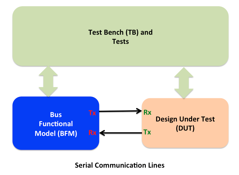
Typical verification environment for serial interface based designs looks as following:
Serial line communication system
Error handling in hardware is verified through the
Error injections on transmit (Tx) side of the bus functional model
Error injection on receive (Rx) side of the bus functional model
Behaving as if the error has been detected on receive side of the bus functional model
Checking response from the DUT on receive (Rx) side bus functional model.
Checking can also be done as part of the monitor which is separate component or built in to the Bus functional model itself
Error injection verification needs a good planning from multiple points of view. They are following:
Error handling in serial communication interfaces is primarily about detecting the corruption in data due to noise in the transmission lines when the data is transmitted from the source to destination. Error detection and handling improves the reliability of the data on unreliable transmission lines.
Some of the errors detected are correctable at the hardware level. Typically such corrections are done through encoding schemes at physical layer level. Error correction here refers to cases where the receiver itself is able to correct it without having to consult the peer. Typically physical layer encoding based error correction can correct errors up to certain predefined number of bits.
This leads to some of the errors that are not correctable at receiver. They require recovery through the retransmission handled by the higher-level protocol layers above physical layer implemented in hardware.
Some of the errors are neither correctable or recoverable at hardware level. These types of errors are detected and reported to software. Software handles the necessary recovery. Reporting to software is handled through set of status registers and interrupts.
The last category of errors that lead to undefined state of the system requiring a physical hardware reset to recover out of it.
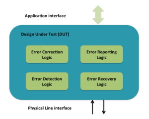
Error handling implementation
Error handling implementation in hardware primarily consists of all or some of the following:
Application interface refers to register and data read/write interface to higher-level software.
Physical line interface is external interface off the chip connecting to another chip.
Error detection logic detects the error. Detection can be based on static pre-defined information or dynamic state information. Undefined protocol data unit type detection is static predefined type of detection. Invalid response or missing response type is state based type of detection. Decoders and timeouts are primary components of error detection logic.
Error correction logic is mostly limited to physical layer encoding schemes. At higher-level layers there is not much of independent error correction involved.
Error reporting logic is typically made up of set of registers and interrupts. Depending on the complexity of error handling different level of granularity of reporting and interrupt generation mechanism is implemented. Group of status registers provides the report on different type of errors detected. For some of errors the transaction causing error is also stored as part of reporting. This helps software with the further diagnosis of the error. Group of mask registers control which errors lead to interrupts. When the total number of errors detected are more than 10 in number they are often grouped in smaller number of categories based on the action for handling them.
Error recovery logic is typically implemented as FSM. In most cases it involves some form of retransmission, re-initialization or resets of different severity based on the nature of the error. Re-transmission is simplest form of recovery where the set of protocol data units not acknowledged are retransmitted. Re-initialization helps re-evaluate any change in the conditions of the physical layer. Reset is more severe form recovery. It can range from just the link reset to entire chip reset.