Author: admin

  • Check-in regressions in Verification

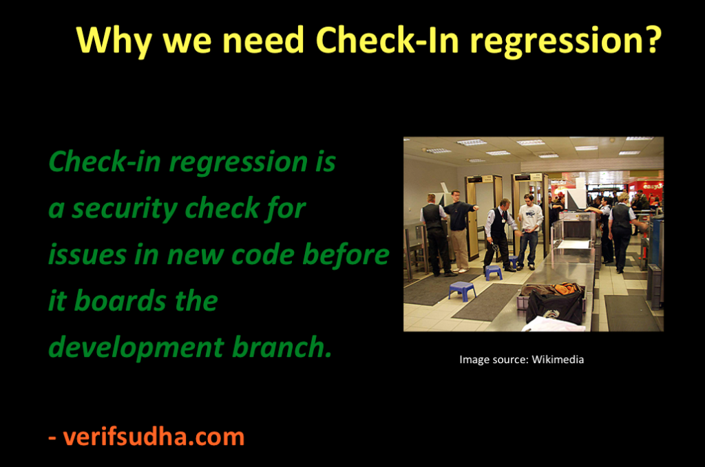
    Regressions are process to keep the passing tests in passing state. Ideally in order to do that full regressions should be run for every change.Since the full regression cannot be run for every change, a selected sub set of tests are run before committing the new changes to development code branch. This subset is called check-in regression. This is expected to minimize the possibilities of the spikes in the failure numbers. This is one of the key component to achieve functional verification quality.

    Screen shot 2016-05-23 at 7.44.10 PM

    Some of the immediate questions about check-in regression would be, how many tests should be selected?  What should be the selection criteria? How long should it run?

    Duration of check-in regression

    Most important question of all is what is the right duration of check-in regression? This is very critical because it limits the speed of the development. Shorter but inadequate check-in regressions may run faster but still slows down development due to failure spikes. Longer but sufficient, may seem right but defeats the purpose of check-in regression. Developers will look for ways to bypass it to avoid the delay. A right balance is the key. Some of the pointers helpful in achieving this balance are discussed below.

    Screen shot 2016-05-23 at 10.27.41 PM


    Thought process for definition of check-in regression

    Check-in regression is all about width and not about depth. It need not go deep in any one area. It should touch all the major features of DUT.

    One of the tools driven approach to selects tests for check-in regression can be based on test grading. Run the full regressions, grade your tests and add the tests that provide the highest coverage. Fair enough. Generally problem may not be simpler. There may be multiple test bench areas. Merging the entire test grading across the test bench areas can sometimes be challenging or simulator you are using may not be supporting it. This is one of the simplest approaches and can be a starting point.

    Test grading based selection is a theoretically correct answer.  That’s because tool can never understand what is really important to your project. Check-in regression should not only broadly cover all the DUT features, but broadly cover features, which are important to project as well. A carefully tailored manual approach is best suited to achieve the best results.

    Manual approach to defining the check-in regression is:

    • List all your test bench areas if there are multiple test benches
    • List all the major configurations parameters and combinations
    • List all the tests grouped under major functional areas: Normal operation, error injection, low power etc.

    Order each of the areas based their importance in DUT use cases. The features and configuration, which are lower on criticality and use cases, will go down in the list.

    Now select few tests from each of the functional areas. Spread them out across the configurations and test benches selected to maximize the unique coverage.

    Effective check-in regression definition is not a one-time process. It’s a continuous process till the chip tape out. Tests have to be swapped, added and deleted to get best coverage per test per unit time. Check-in regression is like plant in pot that needs to be continuously trimmed and cared for to get the best out of it.

    Test selection criteria for check-in regression

    Stability is another very important criteria for test selection in the check-in regression.

    Screen shot 2016-05-23 at 4.19.12 PM

    Typically selection of directed tests are favored over the constrained random tests. That’s because of the stability they offer. Check-in regression instability causes confusion to developers. Developers will soon lose confidence in the check-in regression. Instability leads to slow down in the development process. Check-in regressions stability is one of the critical bottlenecks of the development speed.  

    As long as constrained random tests can also offer reasonable stability they can also be part of the check-in regression. Care should be taken to qualify them sufficiently before making them part of the check-in regression. It should not be qualified as part of check-in regressions. This causes problem for everyone and should be avoided. In fact the constrained random tests chosen for the check-in should be run with sufficient seeds and should be curated for some time as part of full regression. When it starts showing good pass rate it can move in to the check-in regression.

    Tests that run for long duration should be avoided. When there is sufficient compute power available to run tests in parallel, the long running test will become the bottleneck. If its functionality is must for the check-in regressions consider splitting into multiple smaller tests.

    To ensure the shortest run time for selected test ensure that:

    • Logging verbosity of the tests should be set to minimum. Additional logging verbosity can add to run time
    • Code coverage and Functional coverage should not be enabled. It’s not useful with the check-in regressions and adds to execution time.
    • Waveform dumping should not be enabled in check-in regression

    Typically above ones are not violated intentionally but accidentally these can happen. Checks should be put in place to prevent it.

    Simulator selection criteria for check-in regression

    Third party IPs and VIPs vendors have to support it multiple simulators. In such cases tests can be run using the primary simulator in the check-in regression. Compile sanity is sufficient for secondary simulators.

    Primary simulator is the one, which has highest licenses. Including test runs with secondary simulators can potentially lead to license bottlenecks. Only bottleneck for check-in regression should be ideally test run time only.

    Enforcing check-in regression

    Process should be put in place to ensure no code commit to development branch without running the check-in regression. There are cases when developer has run check-in regression and about to commit the code and sees that there is code commits by other developers to the same files. When the updated code is resolved with commits from other developers, check-in regression should be run again. Being pessimistic and paranoid pays.

    It’s tempting to cover lot of things in check-in regression. One need to keep in mind check-in regressions is never going to be fully fool proof. It’s meant to reduce major failure peaks and frequency of such peaks. It is like a bulletproof jacket that can save your life most of the time but cannot guarantee it all the time.

    Effectiveness of check-in regression should be measured by the number of the failure peaks in full regression due to faulty code changes sneaking through check-in regression periodically. If the frequency of failures is unacceptable check-in regression definition process should be repeated and test list should be updated.  

  • Role of Regressions in Verification

    Imagine a floor of the engineers working on design and verification of an interesting DUT. Designers are improving DUT’s strength everyday by adding new features. Verification team is busy catching up with the DUT’s features in test bench. Tests are written for the DUT’s features ready for verification. First milestone is approaching. Required features are ready in DUT, Test bench, BFM and in tests. Tests are executed for features required for milestone. Debug at war pace around for few days. Feature has passed all tests.

    Parents of DUT and test bench are both happy. Little celebrations. Preparations start for next milestone.

    Next question is.. 

    What to do with passing tests?

    If the Newton’s first law of inertia had stayed true in verification by keeping a passing test passing all the time, we did not have to do anything for passing tests. Unfortunately that’s not true.

    Screen shot 2016-05-25 at 3.38.34 PM

    Really, no kidding please. Are you saying, Newton’s first law is not holding up?

    Yes. Passing test will not stay in passing state.

    Why does passing test fail?

    Although test itself is not changing, new seeds, changes to test bench code or DUT code, which is not even directly related to the test can lead to test failures. There is a complex web of dependency between test, test bench and DUT. Sometimes it may not be directly evident.

    Thus a test, which is not changed, can still fail due to changes in other parts of the code. This means there is no guarantee that tests once passing will not stay in passing state. There needs to be effort and process to keep passing tests passing. Yes it may sound bit funny to engineers new to verification. But it’s true. Test in passing state will not stay passing state unless everything is frozen forever. This will not happen unless a company is wrapping up its business.

    What can we do to keep passing test in passing?

    Note that it’s impossible to keep passing test in passing state all the time during development. A passing test will fail several times throughout development cycles to chip tape out. A failure by itself is not bad. As long it is catching issues without significantly affecting forward progress.

    What we do not want is sudden rise in failures, which forces to stop the development till they are fixed. This is bad for schedule as it prevents the forward progress.

    Okay. I get that. But..

    What can be done to increase the chances of keeping passing test passing?

    Yes that’s a right question. We can only strive to improve chances of keeping it in passing state.

    Every new feature being introduced will has potential to cause failure to already passing tests.  This happens, due to incomplete verification of already verified feature. It could be a missed configuration, missed stimulus or missing check for already verified feature. Random seeds or new checks added, new seeds could be leading to discovery of these failures. Another major cause is cross feature interaction. Interaction of the existing features with the new features can discover cases leading to failures in already passing tests.

    Also it’s the humans who are developing the code and not the robots. Human mistakes are bound to happen. It’s not possible to completely eliminate it.

    Regressions are the process to contain and minimize the impact of new changes on already passing tests. Regression in simple words is running all passing tests before every change is committed to development branch. This would ensure no bad changes can come in and passing test remains passing. This is not practically feasible as the number of tests grows. It will not be possible to run all the tests before committing every change to development branch.

    This is not possible because of the time and resource limitations. If the entire regression can be completed within 30 minutes may be one run entire regressions before every check-in. But that’s hardly the case. Entire regressions can range from overnight to few days for any reasonably useful DUT. This delay is not acceptable for qualifying every change. If done can seriously slow down the development.

    One common strategy used is to create a subset of full regression called check-in regression to be run before every code commit to development branch. This is designed to minimize the spikes in the failures of regression. Full regressions are run at a predetermined frequency separately at much lesser frequency than check-in regression.

  • Developer and Debug

    This is a developer’s view of the debug.

    Test failure is an indication that something is not behaving as per the developer’s understanding. All programs work perfectly fine in the developer’s head but fail to function in real world prior to verification.

    Screen shot 2016-05-25 at 6.07.44 PM

    Debugging is a process of finding out difference between the world inside the developer’s head and real world. Developer’s world is perfect.  It’s world free of exceptions. Developer has full control over time and events. Developer loves it.  

    Contrast it with real world filled with exceptions, no control over events or time. Things fall apart. That’s why debugging is so difficult for developers. Note that, it’s not that developer has intentionally created this nice world. It takes time for developer to build the understanding of the real world. Programs cannot wait for full understanding and hence they will fail in real world.

    First mind block for developer is they find it difficult to believe their program is not working. Even when it is failing in real world they look at it from the point of how it would work in their world inside their head. Developers find it hard to imagine what can cause it to not work? First step for developer is to unlearn looking at it from how it can work to start looking at it from how it can fail.

    Developers can live in their world during development but they need come back to real world for debugging. After every debugging they should keep refining the world inside their head with new findings.

  • Scripting

    Verification engineer without good scripting skills is a magician without magic wand.

    Scripting is primarily targeted to solving problems that are not directly related to the functional verification but related to the verification productivity enhancement. That does not mean it should not be used for the functional verification problems as well. It can be but most of functional verification problems are solved using specialized HVLs. HVLs are better suited for that. Typically in the areas where HVLs lack some capability is augmented with the conventional programming languages such as C/C++ rather than scripting languages. It’s changing recently. There are new developments taking place where simulators are providing the native integration to scripting languages. It will be interesting to see how this evolves.

    Scripting can be shell scripting or popular-scripting languages such as Perl, Python or TCL. The idea here is to reach the working prototype very quickly. Many times the scripting solution validity is time limited to certain phase of the project. It’s important to minimize the investments in such scripts and still quickly have a working solution.

    Productivity items can be in any of the four areas of the functional verification planning, development, regression and management.

    In planning, verification plan management is one of the candidates. One of the key requirements is to store the test plan, coverage plan and checks plan in easy to customize form and to match the results from simulation runs.

    In development, code generation can be one big area. Using the design patterns to enhance the code generation is growing fast. Initial development setup generation is a growing application.

    In regression management running regressions, grouping the related failures so that only one of them can be pursued for debugging, regression status generation, and regression failure tracking and linking it with the bugs that have been filed are few problems requiring scripting. This is one of the areas where lot of repetitive activities takes place and hence the need for the automation is quite high.

    In the verification project management the tracking data generation is very important. This data has to be generated periodically. The validity and usefulness of this data is short lived in regression phase. For example the data from weekly lives for a week. There is need for ensure that such reports can be generated automatically. This enables more frequent generation of the reports allowing leaders to stay more current with the execution status in order to make the right decision in time.

    Scripting is one of the integral parts of the functional verification activity. It bridges the gaps in the standard tools. It also helps to build custom flows and tools to provide the edge over the competition.

  • Verification methodology

    Verification methodology provides a framework for easing implementation of coverage driven constrained random verification environments. Verification methodology by itself will not do any functional verification. It’s just an enabler.

    Purpose

    Verification methodology’s primary purpose is to make the adoption of best-known practices of verification easier. The verification environments built according to the methodology provides the consistency in building verification environments.  Verification methodologies restrict the verification environments architecture to certain standard patterns. This restriction allows consistency and standardization when used right.

    Verification methodology also improves the portability. Consistency and portability makes the adoption of the third party vendor solutions easy. Third party BFM usage is one such example.

    Principles

    Modern verification methodology like UVM are built around principles of transaction based verification environments. Note that “transaction” in current context does not always mean the transactions of the communication protocols.

    Transaction is the unit of information packaged together in a class and passed around to the processing elements. Different functional partitions are modeled as processing elements. These processing elements communicate with each other using the transactions.

    Transaction based methodology enables modeling transactions, processing elements, transaction communication channels, and synchronization between the processing elements.

    Scope

    Transaction based framework is foundation of methodology. Flexibility of this framework is improved by using object oriented concepts like inheritance, polymorphism, parameterized classes and static classes. Test simulation time is also managed by methodologies primarily dividing them into pre-test, test-run and post-test phases.  Along with this methodology also provides some of the commonly used utility functionality. Some of the examples of utility functionality are logging, register abstraction layer(RAL) modeling, memory address management(MAM) etc.

    Deployment

    Good part of methodology is it does not stay just in documents. It comes out and plays role hands on. UVM, the current popular verification methodology is deployed through set of the base classes and utility classes implemented in the SystemVerilog. The framework and functionality common across multiple test benches is packaged in these base classes. UVM is used for building user test bench by extending base classes or by using composition of utility classes. In the extended classes, user test bench specific functionality is implemented.

    Case study

    UVM is a transaction driven test bench model. Let’s look at how some of the generic concepts introduced above are implemented in UVM.

    Sequence items are used for modeling transaction. Components act as processing elements. TLM ports are used as communication channel between the components.

    Sequence base class is used for the building the reusable sequences using the sequence items. Sequences are run on the sequencers. Sequencers essentially route the sequence items to right driver. Driver is like BFM, which will drive the sequence item to physical interface.

    Through the phasing mechanism the synchronization of the construction and starting up of the components is implemented.

    Environment is placeholder for all the components. All the components are instanced and integrated in the environment. It provides the global space such as resource and configuration databases for sharing the information across the components and the external world to environment.

    Tests are implemented extending a UVM test base class. Test instances the environment and uses the sequence or sequence items to create the stimulus. Test can obtain handle of any objects, which provide services to test through the config or resource db. These services can also be used for finding out the state of the components for synchronization of the stimulus generation.

    Conclusion

    To conclude verification methodology is pre-established framework for building verification environments. It’s like empty shell of the apartment where the pillars, floors and mechanism to move across the floors is set up.

    Verification engineer will need to understand the requirements of his DUT verification, understand the framework provided by methodology and see how to fit things together. Everything may not fit together, in that one can consider the custom extension the methodology provided functionality as well.

    Verification is a mold. HVLs and methodologies are the metal that should be melted to fit into the mold. Without understanding mold you cannot mold anything.

  • High-level verification language (HVL)

    High-level verification languages can also be termed as domain specific languages.

    Domain specific languages pack more power than the generic programming languages for those domain specific problems. HVLs are no exceptions. HDLs like VHDL or Verilog were primarily targeted towards the RTL design and behavioral modeling.  They were not really designed with the functional verification requirements in mind.

    Whereas HVLs like SystemVerilog have been updated with the functional verification requirements in mind. If you look at the introduction we had seen functional verification is about stimulus generation and response checking.

    Lets look at what are some of key capabilities of SystemVerilog that are specifically targeted to help with the verification. It has all the constructs to implement the coverage driven constrained random verification.

    Stimulus generation: SystemVerilog has support for the randomization and constraints. These two are very powerful constructs that enable a very complex stimulus generations.

    Response checking: SystemVerilog assertions provides a concise and effective way of implementing the checks.

    Functional coverage: SystemVerilog functional coverage construct provides a way to figure out if the interesting scenarios are covered. There is also provision to get the coverage on the assertions, which provide insights into if the checks are active and functioning.  These are some of the key feature directly targeted to help with the verification.

    Object oriented support: SystemVerilog supports object-oriented programming. Object oriented programming improves the code reuse by improving the flexibility of code and maintenance. In fact it’s the OOPs support that has made verification methodologies possible in an elegant way. The concepts of the OOPs such as abstraction, inheritance and polymorphism are used in a different way in verification world than its typically used in the software world.

    Assorted features: Beyond that HVLs will support most of the other popular standard programming constructs. Some of them are enhanced to assist with the task of verification. For example the randcase construct of SystemVerilog is enhancement that makes the randomization based on distribution easier. Associate array data type is best suited for the sparse memory modeling. Queue data type has size construct which can help dynamically size the queues in constraints.

    Easing verification: HVLs orientation toward programming is to make it easy to achieve the verification goals.

  • Tests

    Tests are are the top most layer of verification environment. Tests create the scenarios to verify if the DUT meets the requirement specification. Tests utilize the interface provided by the test bench to achieve the test objective. Common reusable code across tests should be part of the test bench.

    In a constrained random test bench most of the checks are handled by the test bench itself. Highly test specific checks are implemented in the tests. Check implementation within the test should be minimized.

    Tests use reusable stimulus generation sequences provided by the test bench. They constrain the stimulus generators and hooks provided by the test bench to achieve any synchronization required for the complex scenario generation.

    Tests should be written in programmable way. Single feature verification for single configuration is a simple problem. Reality is never simple.  Most tests have to deal with the multiple features and multiple configurations. Tests organization becomes important to optimize the number of tests to cover all of them. We cannot just cover everything under a single constrained random test. Even though its constrained random features have to be spread out across multiple tests with the ability to enable and disable features and program certain specific configurations. This is done in order to manage the complexity.

    Tests should be written such that they can be organized as tree. For example in simple communication interface verification, leaf nodes can be transmit only test, receive only test with node above them can be  transmit & receive concurrent test. A single test could meet all three requirements but it should allow controls to do all three. Doing this type of upfront planning will help reduce the total the files created for the tests. Hence the maintenance effort.

    Tests either by themselves or through the reusable sequences have to take care of completion of the stimulus generation.

    Before starting on the test plan execution it’s important to asses which tests have commonality between them. These tests can be combined into single test with the provision to select the test specific code. This way the code reuse across the tests can be improved.

    Once the tests are coded. Real verification execution starts. This is the major activity and most valuable activity of any verification project. All the test bench is built to see this day. Tests will have to be exercised in different configurations. It may be possible that different configurations of DUT are implemented as  different test benches. Care needs to be exercised to execute the tests in all applicable test bench areas. For constrained random tests based on the state space they are targeting the number of seeds with which it needs to be run is decided.

    If the design does contain low power support through clock gating and multiple power domains, special low power simulations has to be exercised. Tests which do activate these low power sequences have to be selected for the execution under low power simulation.

    If there are multiple instances of the design test has to take care of stimulating all the instances of it.

    A test has to consider creating scenario of interest by stimulating combinations of concurrent interfaces, asynchronous events, getting to right state, right mix of the data stimulus generation and control stimulus generations coupled with the right combinations of features applicable. This has to be exercised across various functional configurations, structural configurations, multiple instances and low power simulations. Based on the state space it additionally needs to be seeded.

    Bottom line every test has primary focus on specific scenario or feature but it has to be covered in lot of secondary variables which have effect on it. Covering the secondary variables has to be achieved through controlling the test variations by programming it or through adding random seeds of the same test.

  • Testbench

    Test bench is an abstracted model of the application world surrounding the  DUT. Test bench also can be thought as a layer of abstraction that translates from  application level to transaction level. BFM, one of the major components of the test bench translates the transaction to physical level to be consumed by the DUT.

    All the verification components are instanced and stitched together in the test bench. One side of the test bench interfaces with the DUT while the other side interfaces to the test.

    Wear verification goggle to see test bench better.

    These test bench components will have to do two things:

    1. Program the application level stimulus in to DUT or BFM
    2. DUT responses checked at different level of abstraction based on its applicability

    Test bench architecture

    Test bench is divided into the following functional areas:

    Testbench architecture : Structural view
    Testbench architecture : Structural view

    Test bench configuration

    Configurations allow configurability of the test bench. There are two types of configurations. Structural and functional configuration.

    Structural configuration provides the configurability of the structure of the test bench. Typically this is done at the start of the simulation. Configurability could be presence or absence of certain interfaces, number of instances of certain interface or design module, Widths of various interfaces etc  

    Functional configuration will provide the configurability of the functionality. Most of the interface specific functional configurability is expected to be handled by the BFMs.  Test bench functional configurability will provide the configurability for application level stimulus generation. For example a specific interface being enabled for traffic generation or certain type of traffic generation disabled for certain other interfaces.  Configurability for the test bench components other than BFMs. For example disabling scoreboard or configuring the interrupt polling frequency or address map for the memory model.

    It’s better to keep both the structural and functional configuration separate. Typically the configurations are designed to be global objects available to all the test bench components.

    Constrained random stimulus generation

    Constrained random stimulus generation at the application level is one the key functionalities of the test bench. There are two key categories of the stimulus generation. First one is the data traffic stimulus generation and second is control event stimulus generation.

    Data traffic stimulus generation mainly targets the DUT’s data path. Typically it’s relatively simpler to implement than control event stimulus generation. Data traffic stimulus generation should take care of generating all the possible types of data traffic and making sure all the programmable variables associated with the data traffic are being exercised to their defined legal range.

    Control event stimulus generation mainly targets the DUT’s control path. These control events alter the data flow. For example consider low power entry and exit scenario of serial communication link. Thought process for control event generation should be no different compared to data traffic stimulus generation. This point is made in the context of flexibility. Control event stimulus generation should be as flexible as data traffic stimulus generation. Its secondary whether the verification ends up enabling and using it in its full glory. Structure should be designed such that the flexibility is not compromised.

    Constraints are key part of the stimulus generation implementation. Remember to randomize as many variables as possible but all randomizations should be test controllable. Deep code buried randomization which are not controllable by test are dangerous. It should not be done.

    Application level to transaction level translations

    This is another major functionality for the test bench. To make this more clear let’s take an example of data transfer using DMA. Basic stimulus generation is data size  and random data to be transferred matching size. DUT would access it through the system memory by fetching data using DMA. For this stimulus to execute data storage space should be allocated in system memory model. Address point and size should be programmed in the DUT. This programming can be through a system bus. Test bench is expected to allocate memory for this stimulus and program the DUT by generating the appropriate transactions on the system bus. Application level stimulus here was the size and random data matching the size. Whereas stimulating DUT with this stimulus requires multiple steps as outlined above which forms the translation logic.

    Depending upon complexity of the translation test bench can also implement it in multiple layers. Each layer doing a part of translation task. Translation logic itself may have certain other control variables which might need randomization. The translation layers variable randomization associated with the stimulus should be made part of the same high level stimulus.

    Scoreboards of different types

    Scoreboards typically do a matching check on related events that cross multiple interfaces. At least two. A transaction left from one interface has it reached the other interface correctly? This type of checks are implemented in the scoreboard.

    Why BFMs themselves do not implement this check as well?

    BFM will be able to do protocol checks localized to a specific interface they are handling. They will not be able to check something which requires knowledge of other interfaces. Anything that requires knowledge of multiple interfaces in order to do the check is handled by the scoreboards in the test bench.

    Scoreboards are the components which are most often used for doing data integrity checks across interfaces. Let’s take a example of a simple protocol bridge like USB to UART protocol converter DUT. This DUT on one side will operate USB and on another side the UART. The individual UART and USB protocol checks will be implemented by the respective BFMs. The data integrity check on the traffic passing through cannot be checked by any single BFM. That’s because the receiving BFM needs the knowledge of the reference data from the transmitted BFM. This is handled by the scoreboard. A scoreboard would gather data from the transmitter BFM which is golden data and compare it with the data received at the receiver BFM which is the actual data. Any discrepancy found will be flagged by the scoreboard as data integrity error.

    Since individual BFMs are capable of doing the lower level protocol checks scoreboard need not be implement them. It’s only needed at the highest level. Ideal is the application level scoreboard.

    Scoreboard concept need not only be limited to data integrity checking. Although that’s the most popular one. Interrupts for instance can be contributed due to variety of causes invoked by different interfaces and combination of the events triggered by different interfaces. This can be checked by building a interrupt scoreboard.

    Any checks to be implemented by collecting information from multiple interfaces is to be handled by test bench. Scoreboard concept is one of the popular way to deal with it.

    Memory  models (Optional)

    It’s hard to imagine a system without CPU. CPUs are everywhere in one form or another. System memory serves CPUs in two ways. First it stores the code and data executed by the CPU. Second it acts as a medium for sharing data between the CPU and peripherals.

    This system memory in test bench is modeled using memory models. They are built around sparse memory concept. Memory models also need address map mangement services.

    Memory address map management services should be able to support

    • Carving out the regions of different attributes
    • Dynamic allocation and deallocation of the memory
    • Identify and support multiple sources of memory access

    Register models (Optional)

    Most of the DUTs interact with the software. Control and status interface of DUTs  is implemented using the registers. Basic register verification requires their accessibility and attributes check. Here the focus is not on the functional aspects but the physical register logic structure implementation checks. The functional aspects of the registers have to be verified through various tests. The randomized test bench functional configuration is typically programmed into the registers to match the expected functional configuration.

    Register abstraction model(RAL) is the way the design’s registers are abstracted in the test bench. This mainly serves two purposes. First it provides the abstraction to tests which shields them from address map changes or physical bus on which registers are accessible changes. Second these RAL model come built in with the certain tests for the checking the accessibility and attributes which are functionality independent.

    BFMs for all the interfaces

    Bus functional model(BFM)s are pillars of the test bench structure. That’s why it’s very important to have a high quality BFMs in the test bench. They are also the engines that power the test bench machinery. BFMs form a layer in test bench which converts the transaction level stimulus to physical stimulus to DUT and vice versa.

    A BFM per physical interface is instanced. If there are multiple physical interfaces multiple BFMs would be instanced. BFM development is described here.

    BFMs are instanced as per the test bench’s structural configuration. The test bench will connect the physical interface of the DUT to the correct BFM instance. The programmable interface of the BFM is used by the verification components of the test bench as well as tests.

    Identifying a clean boundary between the BFM and test bench is a key. Its always advisable for test bench to define its own APIs for accessing the BFM functionality to keep to avoid getting tied down to BFM being used. This abstraction will enable to use the BFMs from the different vendors within the same test bench to gain high confidence over the verification.

    End of test(EOT)

    A good end of test implementation is very important. End of test consists of two components. First one is end of stimulus generation and second is end of stimulus execution.

    Typically end of stimulus generation is determined by the test and end of stimulus execution is determined by the test bench. Test bench creates a common logic that can check with all the components to ensure that stimulus generated has been executed.

    Both of these steps have to wait. Any wait has possibility to become endless. Global watchdog timer will have to be implemented as part of EOT to guard against infinite wait. If EOT does not complete within the configured highest time the test is declared as hung and should be terminated.

    For test to end successfully both of these must complete successfully. Note that successful end of test does not mean test has passed. It means test has completed to end of its execution.

    Clocks and reset generation

    The clocks and resets needed by the DUT are generated in the test bench. Any physical interface specific clocks are typically generated by the corresponding BFMs. It’s the set of the clocks that are not tied to any interfaces will have to be generated by the test bench. Jitter, skew or spread spectrum modeling of the clocks needs to be taken into consideration.

    Multiple resets can be present based on the number of the clock and power domains. These resets may have reset sequencing requirements. Reset sequencing has to be carefully handled by the test bench. Possible delays and scenarios possible with the reset sequencing have to be thought out. This is extremely critical to avoid the dead chips.

    Functional coverage model

    Code coverage is necessary but not sufficient. Functional coverage is equally important to prove the scenarios and configurations we care for are covered thoroughly. Functional coverage model should implement both the types of functional coverage.

    Functional coverage model is clean organization of what to sample and when to sample. A good functional coverage model can help prevent even famous bugs like pentium FDIV bug.  Functional coverage model should be updated whenever bugs are found in uncovered area.

    Did we miss any test bench component?

  • Bus functional models (BFM)

    Bus functional model(BFM) is a model of physical interfaces of the DUT. Presents all the bus level scenario that DUT can experience on the attached bus. BFMs on one side provide the logical interface for the high level transactions interface to test bench components and on another side connect to the physical interface of the DUT.

    Typically the BFM by itself will not generate any stimulus. It has to be directed by the tests or test bench to do so. BFM is implemented adhering to the layered functionality proposed by the specification. Application can also be a layer in the BFM in some of the cases. There are cases where multiple application layer can be supported on single lower layer protocol stacks. Lower layers will be mostly application agnostic.

    BFM on their transmit side support ability to cover both the legal and illegal space. By default, BFM should behave such that on its transmit side it should be able of produce any scenario within the legal bounds of the specification. When directed it should be able to do error injection on the transmit side to verify the error handling behavior of the DUT. Although default operation should be constrained random but all the randomizations within BFM should be controllable by the user.

    On the receive side BFM will check if the DUT behavior is in compliance with the specification. Except for the receive side error injection the default behavior will be in strict adherence to requirement specification. Any deviation from the requirements specification from the DUT’s transmit side will be flagged as error.

    BFM Interface

    BFM should provide interface for implementing the stimulus generation and response checking at bus transaction level.

    • Stimulus generation features
      • Configuration to control the layer’s programmable variables
      • Data and Control transactions at various layers level
      • Error injection at all layers
    • Response checking features
      • Protocol checks at all layers
      • Callbacks at all layers for doing functional coverage and scoreboarding
      • Events for test bench and layer synchronisation
      • Statistics of various events
    • Clean logging for ease of the debugging

    Minimize providing redundant interfaces. That is two types of interfaces for doing the same functionality. Its maintenance nightmare.

    BFM Architecture

    Every layer should be kept separate. It should not be mixed with other layers.

    Data and control interfaces should be kept separate. The data and control interface for both the transmit and receive path should be kept separate.

    Data interface is implemented through the data transaction.  Data transaction will help generate the transaction level data traffic covering the characteristics defined by the specification.

    Control interface is implemented through a control event transaction.  For example, a low power entry or exit request is a control event. It’s possible that data and control interface concurrency may be desired by the specification. BFM design should be able to support that. Concurrent and asynchronous control event support should be well thought out in advance. For example some interface may support issuing a protocol reset in the middle of the traffic.

    Every layer should be cleanly divided into transmit path and receive path. The synchronization between the transmit and receive path can be established through a shared state object. A global configuration object should contain the programmable variables of the layer accessible by both the transmit and receive path.

    Three major paths that should be cleanly divided in all the layers of the BFM are:

    • Data transaction handling separated out for transmit and receive. Transmit covering the spectrum defined by the specification and on receive side implementing strict checks for adherence to the specification
    • Control event transaction for supporting synchronous, asynchronous and concurrent  control events of the bus
    • Error injection implementation consisting of both the transmit and receive side error injection

    Beyond these general rules, the requirements for the BFM architecture should be driven by the verification plan containing test plan, coverage plan and checks plan. BFM should be able to meet the requirements of the verification plan.

    BFM development

    The BFM feature development order should also tie in with the milestones planned for the project execution. This does not mean do a partial BFM architecture. BFM although can be implemented as driven by milestones but the architecture should be thought out completely supporting all the requirements of the verification plan.

    Its best to build the complete skeleton made up of abstract classes. These can be populated based on the feature being implemented. This ensures that as new features added BFM does look patchy. Its still looks as one clean monolithic structure.  

    BFM verification

    Early BFM functionality verification, in some cases can be done by connecting BFMs back to back.  This is fine. Key trap to watch out is false positive pass conditions. For example CRC implementation may be incorrect but as both transmit and receive side implementation is done by single engineer it may still flag it as pass.

    BFMs play a major role in achieving the desired functional verification quality by capturing the specification knowledge in executable form. Now the similar concept can be applied to functional coverage as well by making intent executable in specification to functional coverage generation.

  • Verification goggle

    The way we need a special goggles to see 3D movies clearly,  verification goggles is required to see the verification world correctly.

    Functional verification is about two things: stimulus generation and response checking. Stimulus generated is applied to DUT. DUT’s response to stimulus is checked against the expectations. Every aspect related to verification thus has to be viewed through these two angles.

    Imagine it as a googgle with one lense as stimulus generation and another lense as  response checking. Wear your verification goggle all through your verification activity and it will guide you in the right direction.


    Verification goggle


    The stimulus generation and response checking has to be done at multiple levels of abstractions.