PCI Express PIPE interface functional coverage
What started off, as “PHY Interface for the PCI Express Architecture” was soon promoted to “PHY interface for the PCI Express, SATA and USB3.1 and…
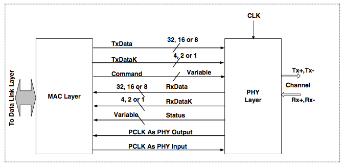
What started off, as “PHY Interface for the PCI Express Architecture” was soon promoted to “PHY interface for the PCI Express, SATA and USB3.1 and SATA”. It was primarily designed to ease the integration of digital MAC Layer with the mixed signal PHY.
Today as of October 2017 latest publicly available PIPE specification is version 4.4.1. All the waveforms and pictures are sourced from this specification. If we go back 10 years in time to 2007, PIPE specification was at version 2.0.
Version 2.0 was for PCI express only. It had only 5 contributors and 38 pages. Whereas version 4.4.1 has 32 contributors and 114 pages. It supports not only PCI express, SATA and USB3.1 as well. Version 4.4.1 has had 5x growth in contributors and 3x growth in number of pages compared to version 2.0.
It’s also indication of rise in complexity of PCI express as well. PCI express has been one of the leading high-speed serial interface technologies. Hence there are multiple IP companies helping with the adoption of the technology. Apart from Big 3 there are also many vendors who provide the PCI express IP solutions. Some provide both the MAC layer and PHY while other provide one of them and partner with complementary vendors to provide the complete solution.
PCI express even at the PIPE interface level has quite a bit of configurability. This comes out in terms of width, rate and PCLK frequencies. Also some companies do make certain level of customization to this interface to support custom features.
To accelerate the simulation speed many verification environments for the PCI express controllers support both the PIPE and serial interface. Parallel PIPE interface runs faster than serial PHY interface. PHY would also require mixed signal simulations as well to verify the analog parts in it.
Considering the complexity there is lot of focus on verifying the MAC layer and PHY layer independently. This creates challenge as to what to verify when they are put together. Obviously it’s not practical to run again all the PHY and MAC layers tests put together on integrated design.
Vendors would make attempt to verify all configurations but do all the configurations get equal attention is something difficult to assess.
When the PCI express IPs are bought from the 3rd party vendors it’s a challenge as to what to cover for integration verification.
PIPE interface coverage can be one of the very useful metric to decide on what tests to run for integration verification. This becomes even more important if the digital controller and PHY are sourced from different vendors.
One can say simple toggle coverage of all the PIPE signals should be sufficient to ensure the correct integration. Yes this is necessary but not sufficient.
Following are some of the reasons why just toggle coverage will not suffice.
- Toggling in all the speeds
Some of the signals of PIPE interface are used only in specific speeds of operation. So it’s important to check for the toggle in appropriate speed. Simple toggle coverage will not indicate in which speed the signals toggled.
Some examples are link equalization signals of the command interface signals such as RxEqEval, RxEqInProgress or 130b block related signals such TxSyncHeader, RxSyncHeader are only applicable for the Gen3 (8 GT/s ) or Gen4(16 GT/s) speeds etc.
- Transition or sequence of operations
Some of the signals instead of just individual toggle coverage require transition or sequence of events coverage to confirm the correct integration.
Some examples are six legal power state transitions, receiver detection sequence, transmitter beacon sequence etc.
- Variation of timing
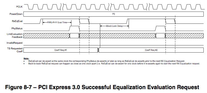
Some of the signals can be de-asserted at different points of time. There can be multiple de-assertion or assertion points that are valid. Based on the design it’s important to confirm the possible timing variations are covered.
For example following waveform RxEqEval can de-assert along with PhyStatus de-assertion or later.
- Concurrency of interfaces
PIPE provides 5 concurrent interfaces, transmit data interface, receive data interface, command interface, status interface and message bus interface.
Simple concurrency like transmit and receive taking place at same time cannot be indicated by the toggle coverage.
- Combinations
Some signals, which are vectors, may not have all the values defined to achieve the toggle coverage.
LocalPresetIndex[4:0] for example has only 21/32 valid values. Here toggle can indicate connection but whether both the digital controller and PHY can handle all combinations of values together is not confirmed.
Also behavior of some key signals in different states needs to be confirmed to ensure the correct integration. TxDeemph[17:0] values will have to be covered based on rate of operation as toggle of all bits may not be meaningful.
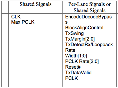
- Multiple lanes
PIPE interface allows certain signals to be shared across multiple lanes. In multi lane case combinations of the lanes active coverage becomes important.
- Multiple times
Some of events or sequences are not sufficient just covered once. Why?
For example in the following waveforms the InvalidRequest must de-assert at the next assertion of RxEqEval. So multiple RxEqEval are required to complete the sequence of the InvalidRequest

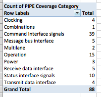
Putting all these together results in functional coverage plan containing 88 cover items.
With our configurable coverage model we can easily customize and integrate all the above covergroups in your verification environment.
We offer service to tell you where your verification stands from PIPE integration coverage point of view.