Testbench architecture – Application world abstraction
Application is the reason for existence of the DUT. Application is combination of the software and hardware. Hardware may be design under test combined with…
Application is the reason for existence of the DUT. Application is combination of the software and hardware. Hardware may be design under test combined with the other designs. Although focus from the verification engineer is design under test (DUT) but it’s important for verification purpose to understand the logical interface of the design to application and how application uses the design. For the purpose of the verification entire application need not be modeled as is. Application world details should be abstracted and relevant details have to be modeled. This abstraction strategy is one of the key areas of the test bench architecture.
That raises question what details of application world is relevant for the purpose of verification?
First let’s quickly understand what are three primary level of abstractions for interacting with the design.
First is the physical interface of pins. This is lowest level interface. Pins will provide ability to communicate binary information.
Second level of abstraction is buses. Bus is a group of pins with set of predefined transactions and protocol to provide certain services. One of the example of service could be simple reliable serial data communication or parallel bus for memory access.
Third level of abstraction is a application interface. Typically built on the top of pins and buses. Its interface for interaction with the application. The user of the DUT. This interface rises far beyond the pins and buses.
Although application paradigm will be different from design to design the fundamental principles behind what needs to be modeled in the test bench remain same. Let’s understand with the popular peripheral interface application abstraction as an example,
Application interface could be simple FIFO interface, DMA access interface or standard specification defined XHCI for USB host controller or UFSHCI type for UFS flash host controller interface. In the context of this discussion, XHCI of UFSHCI stands for of set of data structures to be setup in system memory for telling host controller what to do. For example transfer 10 KB of data needs to be conveyed to host controller through series of predefined data structures.
Lets look at USB Host controller verification problem to make these three levels of abstractions clear. Lets look at this approach for one interface of the DUT. Similar approach should be followed for all interfaces.
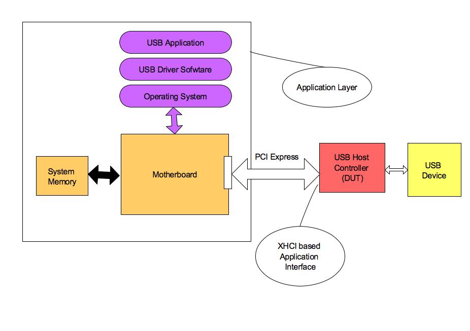
USBx System
The PCI express pins are the level one physical pin interface. PCIe protocol comprising of the physical layer, data link layer and protocol forms the level two a bus interface. The host side interface based on XHCI is level three application interface.
In this case the software driver interacts using the application interface. Typically a PCIe is used for a stand alone USB host controllers to be plugged into the desktop computer.
Note that application layer in the context of this discussion represents entire system behind the PCI express bus shown above. It contains both hardware and software. In terms of hardware, it is CPU, Chipset, System memory and root complex PCI express slot on the motherboard. In terms of software it is the operating system, XHCI based driver and all USB applications. One of them could be flash drive application. End user through a operating system interface may copy, open or delete the files on the attached flash drive.
Now USB host controller(which is DUT) sees all application layer components through the XHCI interface running over the connected PCI express link. How do we model application layer in test bench? Do we need to put a CPU model, run a real driver and application in unit verification simulation?
It needs to be carefully abstracted to the details that matter to DUT verification. We don’t need CPU, real driver and application. DUT just needs the data structures required for the data transfer to setup in the system memory. So test bench should model part of the driver. Test bench needs to model system memory. PCIe link needs to be modeled.
USB application needs to be abstracted to stimulus generation patterns and such stimulus generated using the stimulus generator. The PCIe link will be modeled as a BFM in the verification environment. Don’t worry if you are not familiar with the USB and did not understand some parts of description completely. Point is application layer of real world need not be modeled as it is in test bench. Verification engineers needs to see it through the eyes of the DUT and then model what is relevant for it.
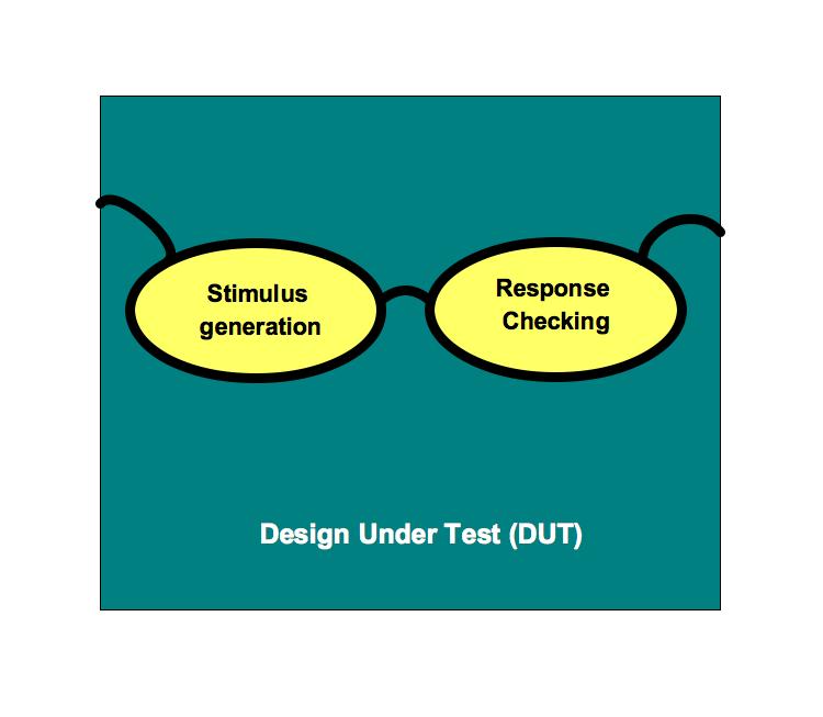
Let’s conclude, complete picture of the verification is all about stimulus generation and response checking at three primary level abstractions. Each of these three levels may contain further sub layers of abstraction depending on the complexity.
Mapping abstractions to verification environment
Let’s now map this picture to verification environments that we see. Tests will create the various scenarios that are possible due to end user actions, operating system or driver actions using the interface provided by the test bench. Test bench will provide interface for tests to generate the stimulus at the application interface level.
Test bench components will convert the stimulus at the application level to transactions supported by the buses to which the stimulus is targeted. These transactions are passed to the bus functional model(BFM). In the above example stimulus generator will generate do transfer 10 KB of data. The test bench components should convert it to series of the data structures as per XHCI specification and set it up in system memory. Pass the pointers about the data structures to DUT through the PCIe bus transactions using PCIe BFM.
BFM will convert the transaction level stimulus to the physical level stimulus to be driven to DUT through its physical level interface. The response of the DUT at the physical level is converted to transactions by the BFMs.
Protocol level checks are implemented within the BFM. Application level checks are implemented in the test bench. Scenario specific checks will be implemented in the tests. In an ideal self checking test bench most of the checks are implemented within the test bench and the BFM.
Verification engineer should see the real world surrounding DUT, through DUT’s eyes wearing verification goggle.
Tasks lists, detailed tasks lists are anchors for the development phase. A good tasks lists provides the more accurate forecasts of the development phase schedules….
Verification plan is process of translating the verification requirement specifications into verifiable description. A verifiable description has to be aligned to technology being used for…
Coverage is one of the important metrics in measuring verification quality and helping with verification closure. Lack of functional coverage can lead to expensive bugs like…
Divide the functionality to various blocks or layers. Map the blocks to classes. Designate the classes as data classes and processing classes. Clearly define the…
According to MSDN, “Software application architecture is the process of defining a structured solution that meets all of the technical and operational requirements, while optimizing common…